Method of manufacturing a stamped biopsy forceps jaw

a biopsy and jaw technology, applied in the field of endoscopic instruments, can solve the problems of reducing the capacity of the jaw, reducing the quality of the jaw, and not producing jaws with thin or very thin sections, so as to eliminate the overbite, improve the repeatability of the thickness of the arm, and eliminate the effect of lateral shi

Active Publication Date: 2007-02-06
MEIER TOOL & ENG
View PDF6 Cites 14 Cited by
  • Summary
  • Abstract
  • Description
  • Claims
  • Application Information

AI Technical Summary

Benefits of technology

[0012]Advantages of the present invention are: elimination of an overbite where one jaw is longer than the other; elimination of lateral shift caused by poor repeatability of the thickness of the arm of the jaw and / or its location; correct positioning of the pivot hole in relation to the plane of the cutting edge thereby eliminating a large gap on both sides of the jaws when the tips of the cups meet, but the backs do not; or the backs of the jaws meet, but the tips do not; elimination of a gap created when the cutting edge of the jaws meet on one side but not on the opposite side resulting from poor control of the perpendicularity of the cutting plane of the jaws to the arm, or a twist of the cup versus the arm; elimination of the gaps between the jaws as a result of irregular cutting planes and or cutting edges; and producing inexpensive yet high quality biopsy jaw forceps that have precise matching of the jaw during closing and obtains excellent quality tissue samples.

Problems solved by technology

Both methods can produce fairly inexpensive components, however due to the nature of the processes the biopsy jaws produced are of low quality.
For instance the casting process does not produce jaws that have thin or very thin sections.
This limitation reduces the capacity of the jaws and limits the size of the specimen that can be obtained.
Furthermore, this method does not produce jaws that have sharp cutting edges and therefore does not have efficient biting capability.
Jaws produced by MIM have thinner sections and sharper cutting edges, however the dimensional and geometrical repeatability of the parts is poor due to the extreme shrinkage of the parts during sintering process.
However, these processes are prohibitively expensive for manufacturing single use instruments.
The method disclosed in Kortenbach however has limited precision as the profile of the cup of the jaw is first cut and then drawn / formed to a spoon like shape.
Furthermore, the prior art has not been able to overcome the following challenges and problems illustrated in FIGS. 1–6, so as to produce or manufacture precise biopsy forceps jaws that have edges that closely match edge to edge when the jaws are in the closed position: overbite where one jaw is longer than the other; lateral shift caused by poor repeatability of the thickness of the arm of the jaw and / or its location; incorrect positioning of the pivot hole in relation to the plane of the cutting edge resulting in a large gap on both sides of the jaws when the tips of the cups meet, but the backs do not; or when the backs of the jaws meet, but the tips do not; a gap created when the cutting edge of the jaws meet on one side but not on the opposite side resulting from poor control of the perpendicularity of the cutting plane of the jaws to the arm, or a twist of the cup versus the arm; gaps between the jaws as a result of irregular cutting planes and or cutting edges; and / or a combination of any or all of the above mentioned problems.

Method used


Image

  • Method of manufacturing a stamped biopsy forceps jaw
  • Method of manufacturing a stamped biopsy forceps jaw
  • Method of manufacturing a stamped biopsy forceps jaw

Examples


Embodiment Construction

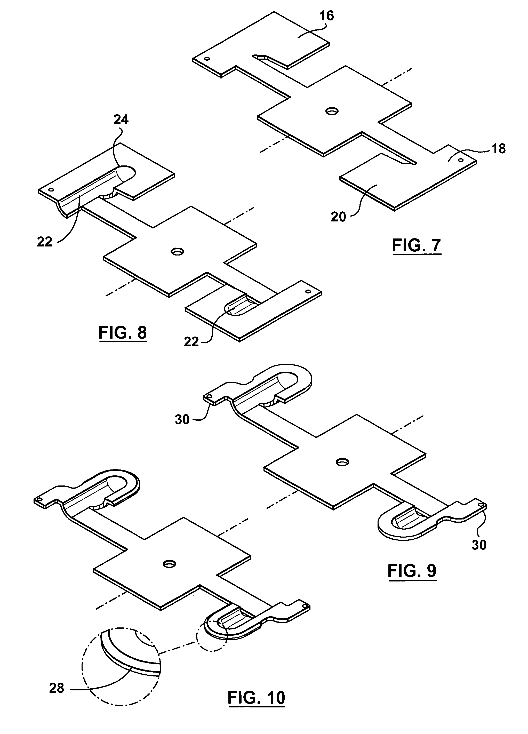
[0035]In accordance with the preferred embodiment of the preferred invention there is provided a method of progressive die stamping for manufacturing a biopsy forceps jaw. Referring to FIGS. 7–9, the method may comprise of the following steps of initially cutting a sheet 10 of metal into a strip 12. The strip of metal 12 may then be punched with a series of guide holes 14. The guide holes ensure accurate positioning of the strip of metal 12 in the progressive die (not shown) during the stamping and drawing process, or press working processes in general.

[0036]A shape 16 that is larger than the actual pattern of the biopsy forceps jaw is then cut or defined into the strip of metal 12. At this juncture in the method, the shape is still attached to the strip of metal. The shape 16 may have a proximal end 18 that is attached to the strip of metal 12 and a distal end 20.

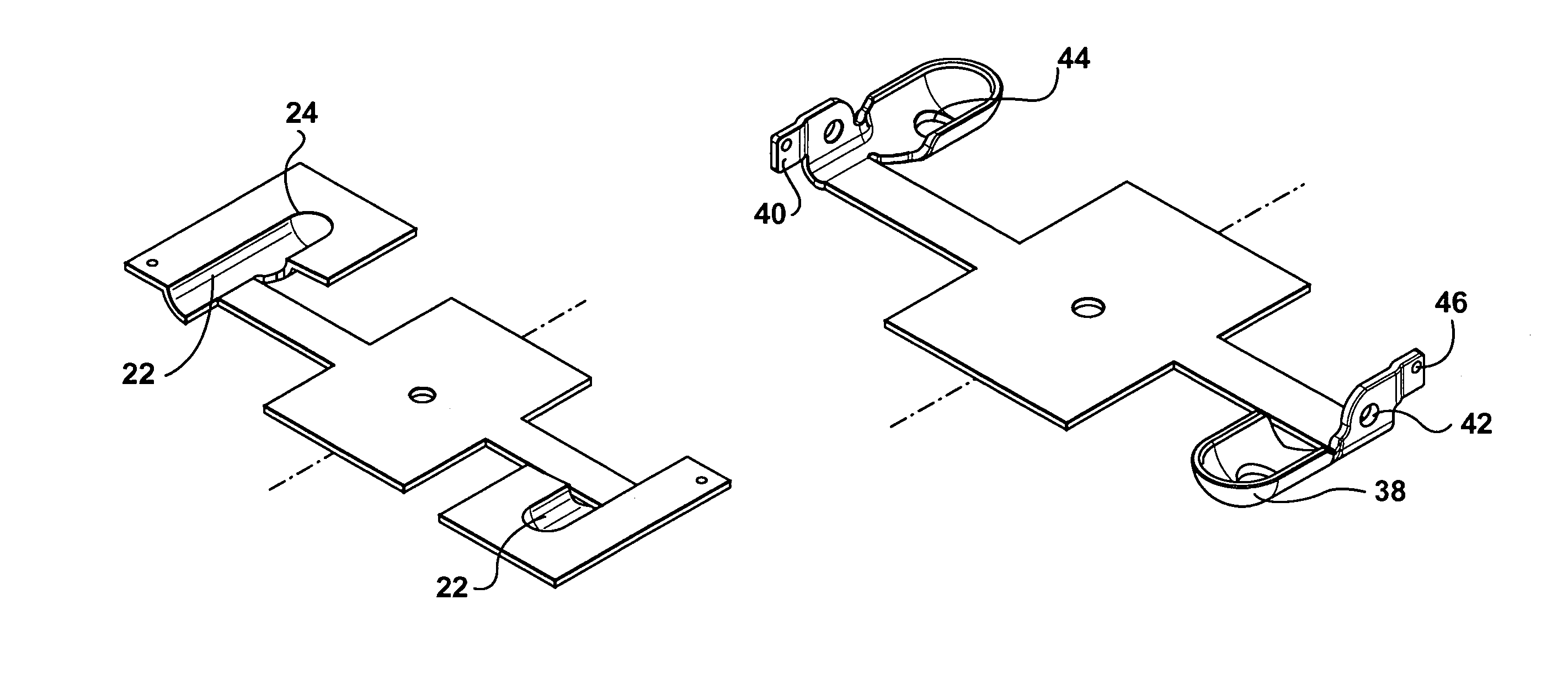
[0037]The next step in the process involves drawing a concave shaped cup portion 22 of the biopsy forceps jaw. In genera...


PUM

PropertyMeasurementUnit
shapeaaaaaaaaaa
sizeaaaaaaaaaa
shrinkageaaaaaaaaaa

Abstract

A method of progressive die stamping manufacturing a biopsy forceps jaw comprising the steps of cutting a sheet of metal into a strip. The strip of metal may then be punched with a series of guide holes. A shape larger than a pattern of the biopsy forceps jaw may then be defined in the strip of metal. An actuating hole may be punched into the shape. A concave shaped cup portion of the biopsy forceps jaw may be drawn. The pattern of the biopsy forceps jaw may then be cut to expose a cutting edge and exposed edges of the pattern. The cutting edge can be coined to provide a hardened, sharp, cutting edge. The exposed edges may be chamfered and then the pattern may be folded and shaped to form a biopsy forceps jaw cup and an arm positioned relative to the biopsy forceps jaw cup. A pivot hole may then be punched into the arm. The biopsy forceps jaw may then go through a calibration so that the cutting edge is in a plane perpendicular to a plane of the arm. The jaw cup may then be cut off of the strip of metal.

Description

FIELD OF THE INVENTION [0001]This invention relates in general to endoscopic instruments and more particularly to a method of manufacturing a stamped biopsy forceps jaw in a more cost efficient manner, thereby producing a superior product that allows for obtaining high quality tissue specimens.BACKGROUND OF THE INVENTION[0002]With the increased vigilance in infection control and the detection of new transmittable diseases, there is a need for disposable or single use biopsy forceps devices. Presently, the disposable and inexpensive biopsy forceps have jaws that may be made by either a casting method or through powder metal injection molding (MIM). Both methods can produce fairly inexpensive components, however due to the nature of the processes the biopsy jaws produced are of low quality. For instance the casting process does not produce jaws that have thin or very thin sections. This limitation reduces the capacity of the jaws and limits the size of the specimen that can be obtaine...

Claims


Application Information

Patent Timeline
Patent Type & Authority Patents(United States)
IPC IPC(8): B21D31/00B21D28/00A61B10/00A61B10/06A61B17/00B21D22/02B21D35/00B21D53/00
CPCA61B10/06B21D35/00A61B2017/00526
Inventor KRZYZANOWSKI, JACEK
Owner MEIER TOOL & ENG
Why Eureka
Try Eureka