
Electric potential sensor for use in the detection of nuclear magnetic resonance signals

a nuclear magnetic resonance and potential sensor technology, applied in the field of electric potential sensors, can solve the problems of system recovery from overload, physical and electronic constraints, and unnecessary introduction of constraints on the system performance,

Inactive Publication Date: 2011-04-12
THE UNIV OF SUSSEX
View PDF7 Cites 2 Cited by
  • Summary
  • Abstract
  • Description
  • Claims
  • Application Information

AI Technical Summary

Benefits of technology

[0026]The problem of cross coupling between transmitter and receiver coils in the conventional apparatus is avoided, thereby reducing recovery and dead times in the receiver system.
[0029]Smaller probe sizes reduce filling factor problems, which exist in conventional systems, allowing the imaging of very small sample volumes.

Problems solved by technology

This necessarily introduces constraints, both physical and electronic on the performance of the system.
Further, an inherent electronic problem associated with the traditional approach is that the transmitter coil couples to the receiving coil inductively, leading to saturation of the receiver amplifier and a subsequent dead time during which the system recovers from overload.
However, despite these measures the inherent difficulty remains that a large amplitude RF transmitter pulse must be coupled to the sample, and that a small but significant proportion of this will couple inductively to the receiver coil and hence saturate the amplifier system.

Method used


Image

  • Electric potential sensor for use in the detection of nuclear magnetic resonance signals
  • Electric potential sensor for use in the detection of nuclear magnetic resonance signals
  • Electric potential sensor for use in the detection of nuclear magnetic resonance signals

Examples


Embodiment Construction

Theory of the Use of Electric Potential Sensors

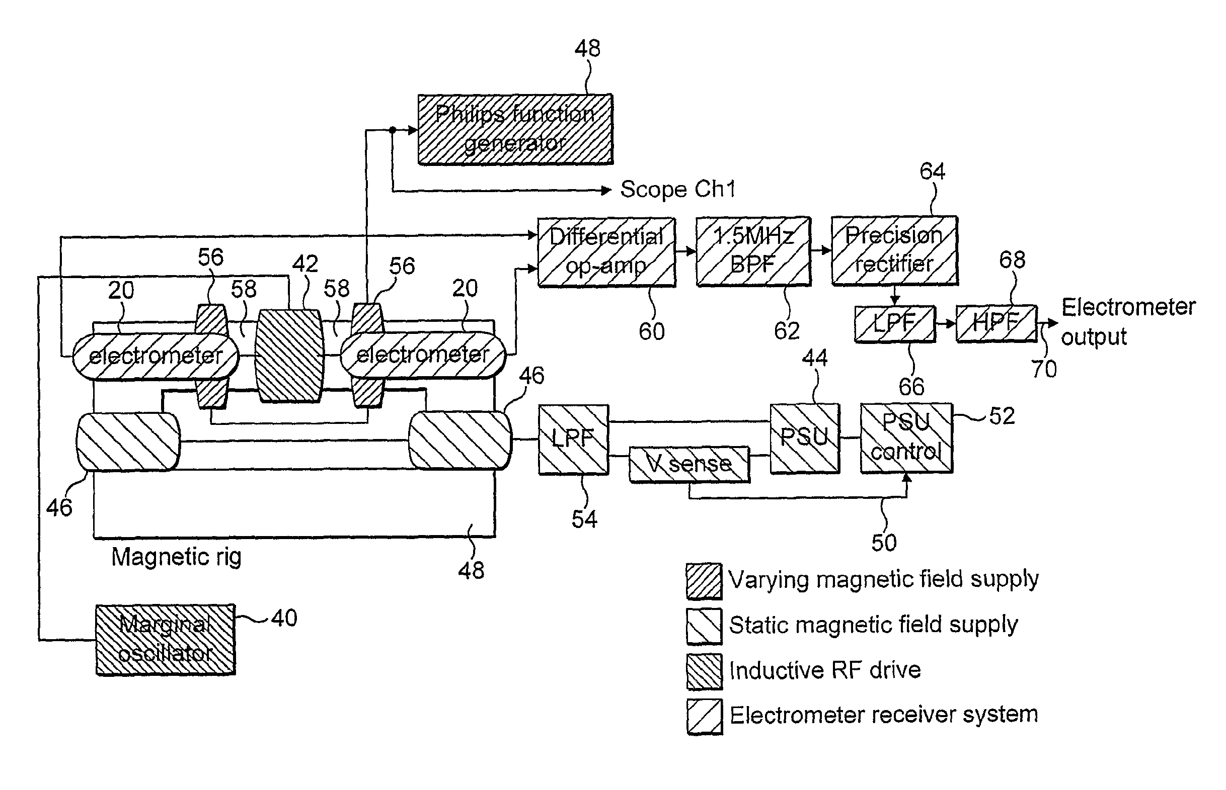
[0047]The present invention proposes to employ an electric field sensor in place of the known inductive sensor arrangement of FIG. 2 for signal detection in NMR apparatus.

[0048]The principle of operation for electric field detection of NMR signals is to utilise the electric field (E) associated with the precessing magnetic field (B) of the nuclear spins. From the theory of electromagnetism for the far field approximation of a dipole, it is known that:

|E|=c|B|

where c is the velocity of light. According to the present invention, an electric field sensor is provided for coupling, via a capacitive mechanism, to a sample in order to acquire the NMR signal.

[0049]The electric field vector (E) is perpendicular to the magnetic field component (B) and rotating at the Larmor precession frequency. Formally, the two components are related by a Maxwell equation:

Curl E=−δB / δt

[0050]This provides the information needed to position an electrode arrangem...


PUM


Abstract

The present invention provides nuclear magnetic resonance apparatus comprising means for applying a static magnetic field (H0) to a sample under investigation, a radio frequency circuit arranged to be inductively coupled to the sample by means of an oscillating magnetic field disposed generally perpendicular to the static magnetic field for applying an excitation signal to the sample, and an electric potential sensor (E1, E2) for detecting the excitation of the sample and for generating a detection output. The electric potential sensor comprises an electrode placed generally perpendicular to the axis of the oscillating magnetic field for capacitively coupling the electric potential sensor to the sample.

Description

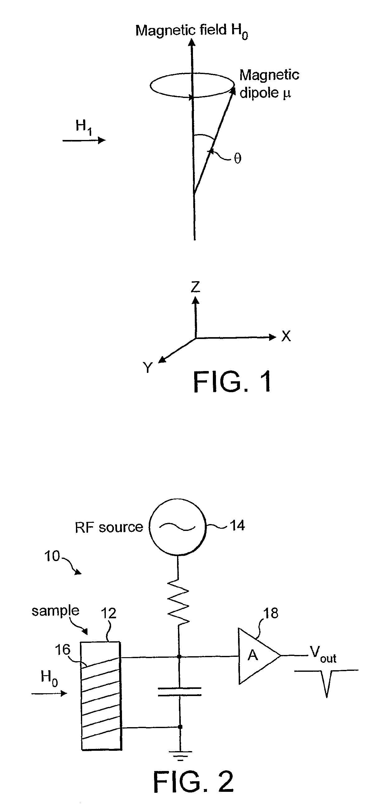
FIELD OF THE INVENTION[0001]The present invention concerns electric potential sensors for use in the detection of signals generated in nuclear magnetic resonance (NMR) apparatus, as well as to a method of NMR signal detection.[0002]The invention may find application in numerous areas, for example in NMR imaging and spectroscopy, and in quantum computers, as well as in medical applications such as Magnetic Resonance Imaging (MRI).BACKGROUND TO THE INVENTION[0003]Nuclear magnetic resonance (NMR) is a phenomenon which occurs when the nuclei of certain atoms are subjected to a magnetic field in the presence of a second, perpendicular, oscillating magnetic field, and this phenomenon is commonly employed in NMR imaging and spectroscopy to study the physical, chemical or biological properties of samples of matter. This may best be understood by reference to FIG. 1.[0004]Many species of nuclei contain non zero spin and an associated magnetic dipole moment, and it is this which gives rise to...

Claims


Application Information

Patent Timeline
Patent Type & Authority Patents(United States)
IPC IPC(8): G01V3/11
CPCG01R33/323G01N24/08G01R33/445G01R33/3657G01R33/3621
Inventor PRANCE, ROBERTCLARKE, TERENCE
Owner THE UNIV OF SUSSEX
Learn More