
Method of printing with high spot placement accuracy

a spot placement accuracy and spot placement technology, applied in the direction of printing, conductive pattern formation, circuit inspection/indentification, etc., can solve the problems of reducing yield, inconsistent device performance, and no suitable method for soldermask patterning using laser direct imaging, so as to achieve accurate spot placement, high addressability, and high spot placement accuracy

Active Publication Date: 2011-04-19
XEROX CORP
View PDF8 Cites 4 Cited by
  • Summary
  • Abstract
  • Description
  • Claims
  • Application Information

AI Technical Summary

Benefits of technology

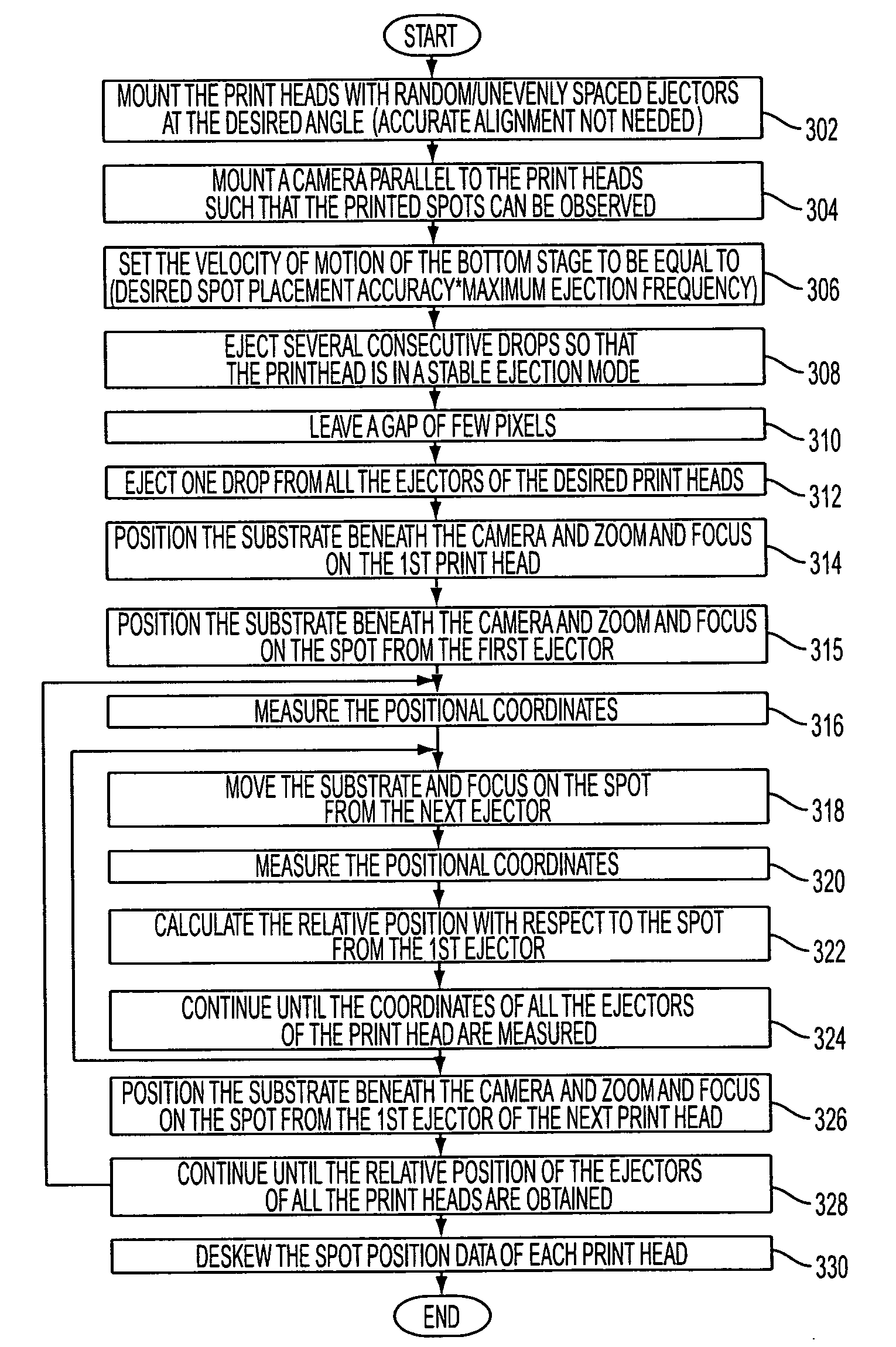
[0014]Disclosed herein is a method of printing spots with high spot placement accuracy using print heads with random / unevenly spaced ejector locations and coarse alignment of the multiple print heads. This is performed by accurately determining the spot positions from all the print heads using a vision system and printing at high addressability. The spot placement accuracy will be determined by the addressability as long as the spot position is reproducible and other system errors are negligible.

Problems solved by technology

Also, there is no suitable method for soldermask patterning using laser direct imaging, which is the final crucial lithography step in PCB manufacturing.
Failure to have good spot placement accuracy can result in patterning defects, which can reduce the yield and lead to inconsistent device performance.
However, some of the commercial print heads available in the market have high density of unevenly spaced ejectors.
While the high density of ejectors is a desirable feature, the unevenly spaced ejectors are not.
This limits the number of ejectors that qualify for printing and therefore reduces the advantage of having high density of ejectors in the print head.
Some of the print heads have offsets in the ejector locations, which may be deliberately introduced or caused by other production limitations.
However, if some of the ejectors are not in the ideal location of the 169.32 μm but have an offset, the printed spots will have a spot placement accuracy limited by the offset when printed at 150 DPI.

Method used


Image

  • Method of printing with high spot placement accuracy
  • Method of printing with high spot placement accuracy
  • Method of printing with high spot placement accuracy

Examples


Embodiment Construction

[0029]Some portions of the detailed description that follows are presented in terms of algorithms and symbolic representations of operations on data bits performed by conventional computer components, including a central processing unit (CPU), memory storage devices for the CPU, and connected display devices. These algorithmic descriptions and representations are the means used by those skilled in the data processing arts to most effectively convey the substance of their work to others skilled in the art. An algorithm is generally perceived as a self-consistent sequence of steps leading to a desired result. The steps are those requiring physical manipulations of physical quantities. Usually, though not necessarily, these quantities take the form of electrical or magnetic signals capable of being stored, transferred, combined, compared, and otherwise manipulated. It has proven convenient at times, principally for reasons of common usage, to refer to these signals as bits, values, ele...


PUM


Abstract

A method of printing spots with high spot placement accuracy using print heads with random / unevenly spaced ejector locations and coarse alignment of the multiple print heads. This is performed by accurately determining the spot positions from all the print heads using a vision system and printing at high addressability. The spot placement accuracy will be determined by the addressability as long as the ejected drop position is reproducible and other system errors are negligible.

Description

BACKGROUND[0001]A printed circuit board, or PCB, is a self-contained module of interconnected electronic components found in devices ranging from common beepers, or pagers, and radios to sophisticated radar and computer systems. The circuits are generally formed by a thin layer of conducting material deposited, or “printed,” on the surface of an insulating board known as the substrate. Individual electronic components are placed on the surface of the substrate and soldered to the interconnecting circuits. Contact fingers along one or more edges of the substrate act as connectors to other PCBs or to external electrical devices such as on-off switches. A printed circuit board may have circuits that perform a single function, such as a signal amplifier, or multiple functions.[0002]Two other types of circuit assemblies are related to the printed circuit board. An integrated circuit, sometimes called an IC or microchip, performs similar functions to a printed circuit board except the IC ...

Claims


Application Information

Patent Timeline
Patent Type & Authority Patents(United States)
IPC IPC(8): B41J29/393
CPCB41J2/2139H05K3/125H05K1/0269H05K2203/163H05K2203/013H05K3/0008H05K3/12
Inventor SRINIVASAN, UMAFITCH, JOHN STUARTREADY, STEVEN E.
Owner XEROX CORP
Learn More