Supercharge Your Innovation With Domain-Expert AI Agents!

Method and apparatus for molding with reduced cull formation

a technology of cull formation and molding, applied in the field of molding system, can solve problems such as inability to completely eliminate cull

Active Publication Date: 2011-04-19
ASMPT SINGAPORE PTE LTD
View PDF15 Cites 1 Cited by
  • Summary
  • Abstract
  • Description
  • Claims
  • Application Information

AI Technical Summary

Benefits of technology

"The invention aims to provide a molding apparatus and process that reduces the amount of waste during the molding of semiconductor devices. The apparatus includes a plunger assembly and a runner connected to a mold supply pot for channeling the molding compound to the electronic devices. The width of the opening connecting the runner to the mold supply pot is smaller than the width of the main body of the plunger assembly. The method involves locating the plunger assembly in the mold supply pot and then driving it towards the runner to force the molding compound into the runner. This reduces the amount of waste during the molding process and improves the efficiency of the process."

Problems solved by technology

However, it cannot totally eliminate cull because there is still a substantial amount of molding compound that remains between the plunger and a recess in the mold chase corresponding to the position of the mold supply pot even after the plunger applies maximum pressure.

Method used


Image

  • Method and apparatus for molding with reduced cull formation
  • Method and apparatus for molding with reduced cull formation
  • Method and apparatus for molding with reduced cull formation

Examples


first embodiment

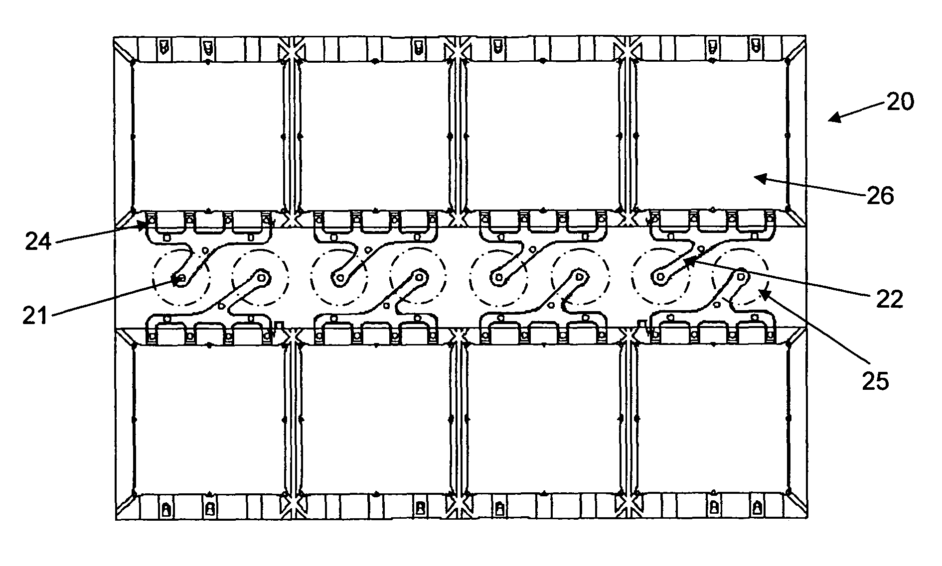
[0026]FIG. 5 is a cross-sectional view of a plunger assembly 30 of the molding apparatus. The plunger assembly 30 comprises a main body or main plunger 32, which may be shaped and sized externally like a conventional plunger of the prior art. The main plunger 32 has a top surface 34 that is configured to crush and to apply pressure on a pellet of molding compound in the mold supply pot 25 to force the molding compound into the runners 22, gates 24 and molding cavities 26. The plunger assembly 30 has a hole 37 that is aligned with a central axis 38 of the plunger assembly 30. Preferably, the hole 37 extends throughout the length of the main plunger 32.

[0027]A major innovation in the preferred embodiment is a supplementary body or inner plunger 36 located in the hole 37. The inner plunger 36 is movable relative to the main plunger 32 along the hole 37, and in one preferred embodiment of the invention, is drivable to travel beyond the top surface 34 as well as be retracted behind the t...

second embodiment

[0032]An operation of the second embodiment is now described. The plunger assembly 30 is first moved upwards so that the top surface 34 compresses a pellet of molding compound in the mold supply pot 25. The plunger assembly 30 is forced upwards until the top surface 34 comes into contact with a surface of the mold chase 20. Meanwhile, molding compound is forced into the runners 22, gates 24 and molding cavities 26. If the inner plunger 36 is flush with the top surface 34, some molding compound may tend to be forced into the hole 37 due to a reaction force produced by the molding compound being compressed. However, this reaction force is counterbalanced by the preloaded biasing force from the spring 40 acting on the spring flange 42 of the inner plunger 36. Typically, it is expected that some molding compound would tend to flow into the hole 37 under this arrangement, but the amount of flow is controllable.

[0033]After the molding compound has hardened and when the plunger assembly is...


PUM

PropertyMeasurementUnit
diameteraaaaaaaaaa
movementaaaaaaaaaa
widthaaaaaaaaaa

Abstract

An apparatus and process are provided for molding electronic devices in a mold, which apparatus comprises at least one runner in the mold connected to a mold supply pot for channeling a molding compound from the mold supply pot to the electronic devices. A plunger assembly is also provided that comprises a main body, and a supplementary body configured to be movable relative to the main body. The plunger assembly is locatable in the mold supply pot and is drivable in a direction towards the runner for forcing the molding compound into the runner. In order to avoid or reduce cull formation, a width of the runner at an opening connecting the runner to the mold supply pot is smaller than a width of the main body of the plunger assembly.

Description

FIELD OF THE INVENTION[0001]The invention relates to a molding system for the encapsulation of semiconductor devices with molding compound.BACKGROUND AND PRIOR ART[0002]During the assembly of semiconductor packages, semiconductor chips are often attached onto carriers, such as substrates or leadframes. After or during attachment, electrical connections are made between electrical pads on the chips to corresponding contacts or connection pads on the substrates or leadframes. This can be done by wire bonding, or the electrical pads can be directly attached onto the contacts on the substrates or leadframes. Thereafter, it is usually necessary to protect the chips and the electrical connections by encapsulating them in an encapsulation compound, such as epoxy molding compound (“EMC”).[0003]In a typical transfer molding process, the substrate or leadframe with the chips attached is placed into a molding system comprising two mold halves. One or more molding cavities are formed in one or ...

Claims


Application Information

Patent Timeline
Patent Type & Authority Patents(United States)
IPC IPC(8): B29C45/00
CPCB29C45/02B29C45/586B29C45/27B29C45/14655
Inventor CHEN, XIANGHO, SHU CHUENKUAH, TENG HOCK ERICLU, SI LIANGONG, SEE YAP
Owner ASMPT SINGAPORE PTE LTD
Features
  • R&D
  • Intellectual Property
  • Life Sciences
  • Materials
  • Tech Scout
  • Unparalleled Data Quality
  • Higher Quality Content
  • 60% Fewer Hallucinations
Learn More