Ultra-wide angle objective lens

a wide-angle, objective technology, applied in the field of compact lenses, can solve the problems of large lens assembly, difficult or impossible to design lenses that meet equation 1, and the prior art design of wide-angle lenses tends to have a significant amount of optical distortion

Active Publication Date: 2011-04-19
NING ALEX
View PDF9 Cites 40 Cited by
  • Summary
  • Abstract
  • Description
  • Claims
  • Application Information

AI Technical Summary

Benefits of technology

[0017]A second performance objective in the design is to achieve excellent optical performance up to 180° field of view and having a f / # as low as 2.0 and with a minimum number of lens elements.

Problems solved by technology

Prior art designs of wide-angle lenses tend to have a significant amount of optical distortion.
However, the lens assembly is large, heavy and expensive to produce because of the large number of elements used.
However, as the field of view required increases, it becomes more difficult or impossible to design lenses that satisfy Equation 1.

Method used


Image

  • Ultra-wide angle objective lens
  • Ultra-wide angle objective lens
  • Ultra-wide angle objective lens

Examples


Embodiment Construction

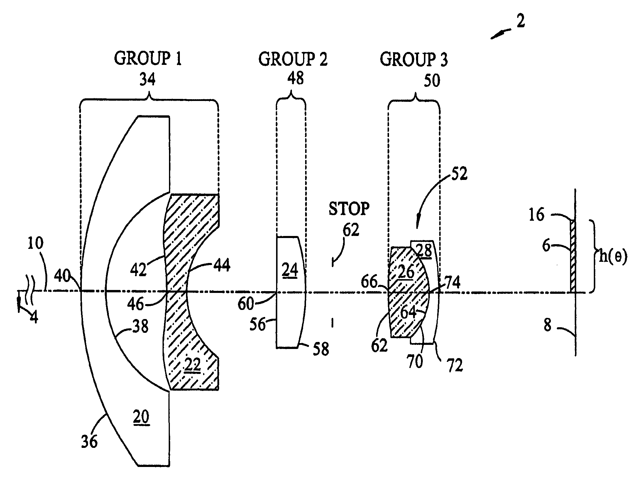
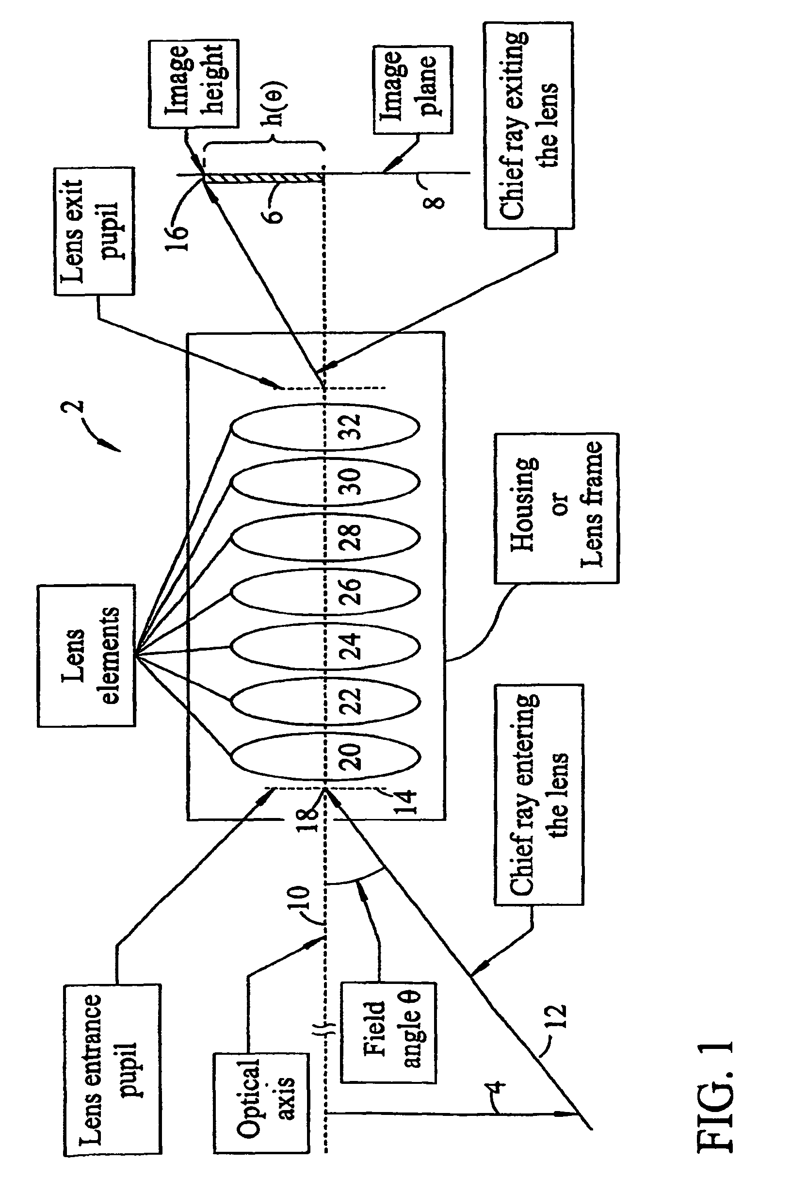
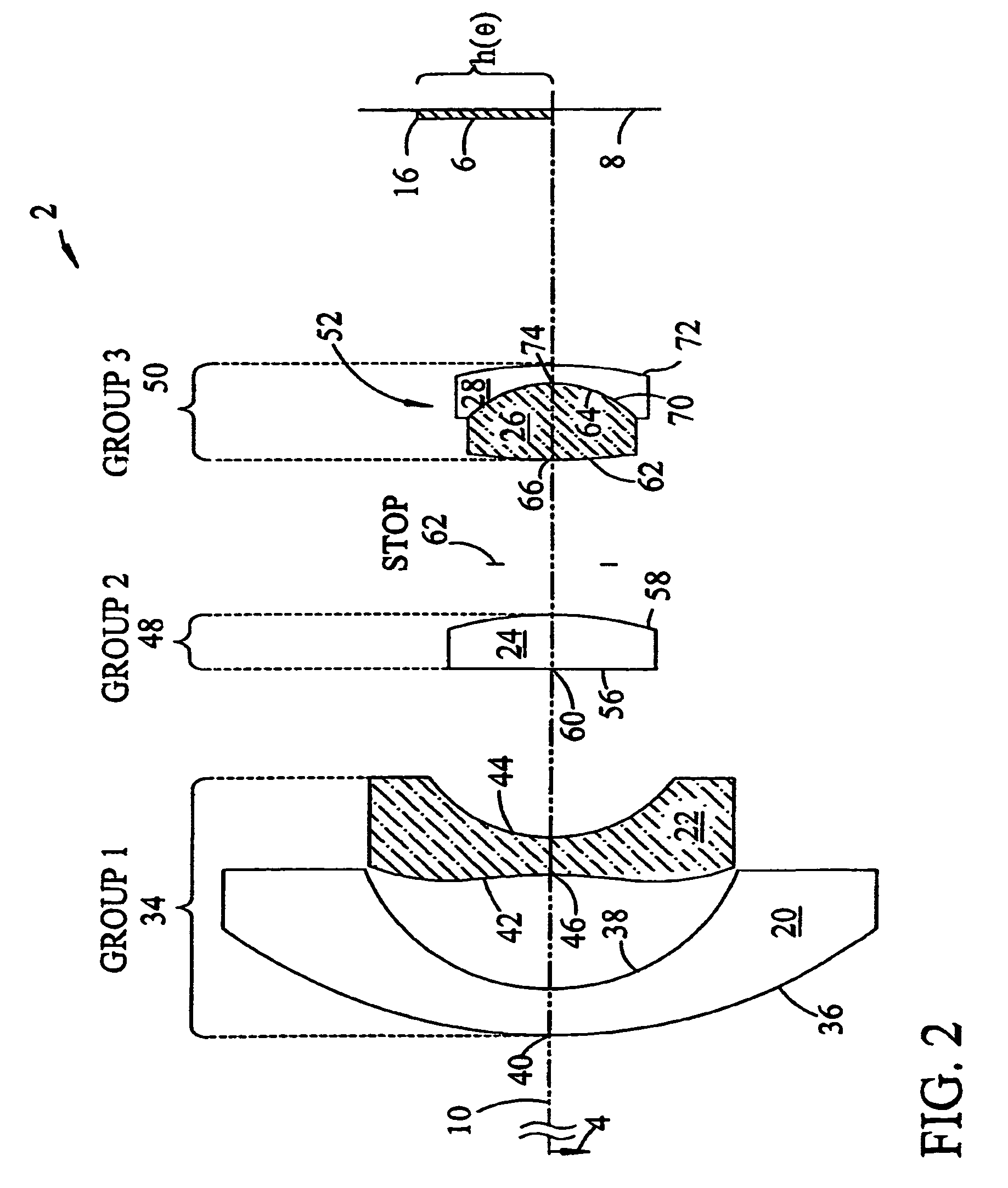
[0026]FIG. 1 is a generalized schematic of the invention ultra-wide angle objective lens 2 that receives light from object 4 which is shown pointing downward at the left of FIG. 1 in object space at an infinite distance from the ultra-wide angle objective lens 2. The ultra-wide angle objective lens 2 uses the light from object 4 to form an image 6, of the object 4, on the image plane 8.

[0027]The legend “Lens Entrance Pupil” is one of the several legends, each of which define an added feature on the optical schematic. The “optical axis” legend identifies the optical axis 10. The “field angle “θ” legend identifies the angle that a chief ray 12 makes with the optical axis 10 as the chief ray 12 enters the lens entrance pupil 14 The legend “Image height” locates the top of the image 16. The height of the image “h” is the distance from the optical axis 10 to the top of the image 16.

[0028]the chief ray 12 extends to the lens center at the entrance pupil center 18 and thereafter progresses...


PUM


Abstract

A ultra-wide angle objective lens comprising a first group having a first lens element having a convex object surface facing the object and a concave image surface facing the image plane, and a second aspheric lens element, the second aspheric lens element having a varying power that is negative at its vertex; and that increases positively with radial distance from the vertex. A second group has at least one lens element and a positive power. A third group has at least a first and a second lens element and a positive power. The ratio of the total track to the focal length satisfies the condition that TT / fo=<33 and the image height on a focal plane is h(θ)>f*θ, where h(θ) is the image height formed by an off-axis chief ray having a field angle θ, and f is the effective focal length of the lens.

Description

[0001]The application claims priority from U.S. provisional application 60 / 791,032 filed Apr. 10, 2006 for an Ultra-Wide Angle Imaging Lens having a common inventor.STATEMENT REGARDING FEDERALLY SPONSORED RESEARCH OR DEVELOPMENT[0002]Not applicableTHE NAMES OF THE PARTIES TO A JOINT RESEARCH AGREEMENT[0003]Not applicable.INCORPORATION-BY-REFERENCE OF MATERIAL SUBMITTED ON A COMPACT DISC[0004]Not applicableREFERENCE TO A “MICROFICHE APPENDIX”[0005]Not applicable.REFERENCE TO SEQUENCE LISTING[0006]Not applicable.FIELD OF THE INVENTION[0007]This invention relates to compact lenses for digital camera applications and, in particular, to very wide angle or fisheye lenses for very compact digital cameras. Such lens designs are incorporated into security cameras and other very small electronic devices.BACKGROUND OF THE INVENTION[0008]Imaging lenses with ultra wide field of view (with full field of view>=100°up to 180° FOV fisheye lenses) are required for many applications. Fisheye lenses...

Claims


Application Information

Patent Timeline
Patent Type & Authority Patents(United States)
IPC IPC(8): G02B13/04G02B13/18
CPCG02B9/60G02B13/18G02B13/06G02B9/62
Inventor NING, ALEX
Owner NING ALEX
Why Eureka
Try Eureka