Transfer device and image forming apparatus using the same

a technology of transfer device and image forming apparatus, which is applied in the direction of electrographic process apparatus, instruments, optics, etc., can solve the problems of reducing and affecting the performance of secondary transfer belt cleaning. , to achieve the effect of improving the performance of secondary transfer belt cleaning

Inactive Publication Date: 2011-04-19
SHARP KK
View PDF9 Cites 4 Cited by
  • Summary
  • Abstract
  • Description
  • Claims
  • Application Information

AI Technical Summary

Benefits of technology

[0009]The present invention has been achieved in view of the above circumstances, it is therefore an object of the present invention to provide a transfer device and an image forming apparatus including the transfer device, wherein the amount of static charge on the toner on the transfer belt is restored so as to constantly stabilize the ability to clean the secondary transfer belt and shorten cleaning time.
[0014]In the transfer device of the present invention, the controller may be constructed so as to cause the pre-transfer charging unit to vary the drive condition of charging based on the total print count.
[0018]The transfer device of the present invention and the image forming apparatus including this device have the excellent effect as follows.
[0019]According to the transfer device of the present invention, when the amount of static charge on the developer is expected to be lowered, charge radiation from the PTC is effected over the primary transfer belt so as to restore the amount of static charge on the toner over the belt, whereby it is possible to constantly stabilize the performance of cleaning the secondary transfer belt and reduce the cleaning time.
[0020]Further, according to the transfer device of the present invention, it is possible to remove the unnecessary toner that appears when image patches are formed at the time of image quality control for the image forming apparatus.
[0021]Also, according to the transfer device of the present invention, it is possible to remove the unnecessary toner that appears when one print job in the image forming apparatus has been finished.

Problems solved by technology

When a transfer scheme of this kind is adopted, “fogging toner” caused by residual potential other than the toner image transfers to the transfer belt, causing soil on the transfer belt.
However, when the transfer belt to be cleaned is thin and soft, it is not beneficial to abut and press a hard blade against the transfer belt of this kind because various problems such as occurrence of wrinkles in the belt, occurrence of meandering of the belt and in the worst case, a rupture of the belt occur.
However, when electric cleaning of the secondary transfer belt (causing the residual toner to return from the secondary transfer belt to the primary transfer belt side) is performed in the above way, this method suffers the problem that if the amount of static charge has lowered due to deterioration of the developer (toner) or exposure of the developer to high humidity environments, the cleaning performance lowers hence the toner fails to return from the secondary transfer belt toward the primary transfer belt.

Method used


Image

  • Transfer device and image forming apparatus using the same
  • Transfer device and image forming apparatus using the same
  • Transfer device and image forming apparatus using the same

Examples


Embodiment Construction

[0028]An embodied mode of a transfer device of the present invention and an image forming apparatus including this will hereinafter be described with reference to the accompanying drawings.

[0029]FIGS. 1 to 6 are views showing one example of the embodiment of a transfer device according to the present invention and an image forming apparatus including this. In the drawings, the components allotted with the same reference numerals will represent identical components.

[0030]To begin with, the overall configuration and operation of the image forming apparatus will be briefly described before giving description on the specific configuration and operation of the transfer device according to the present invention.

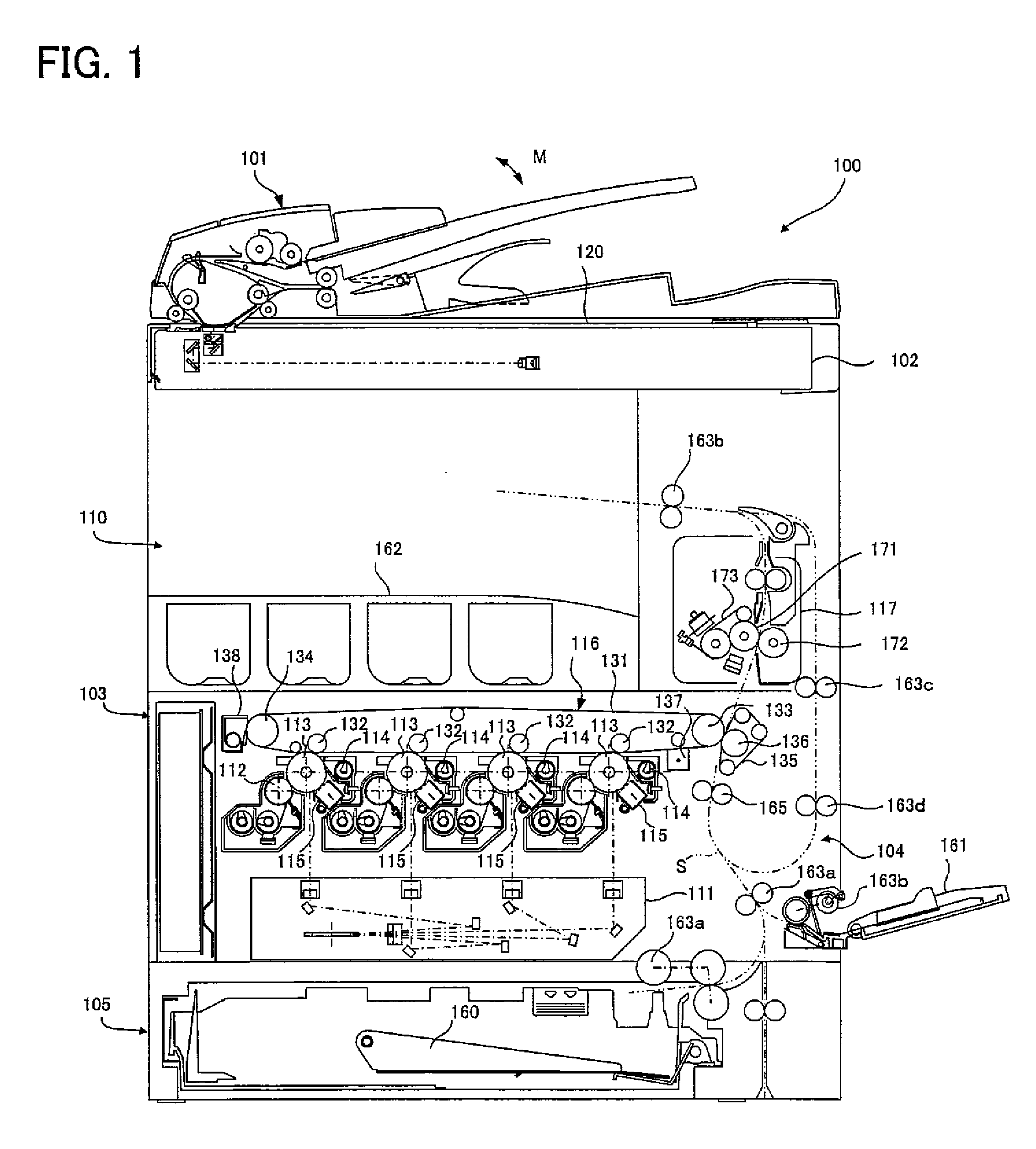
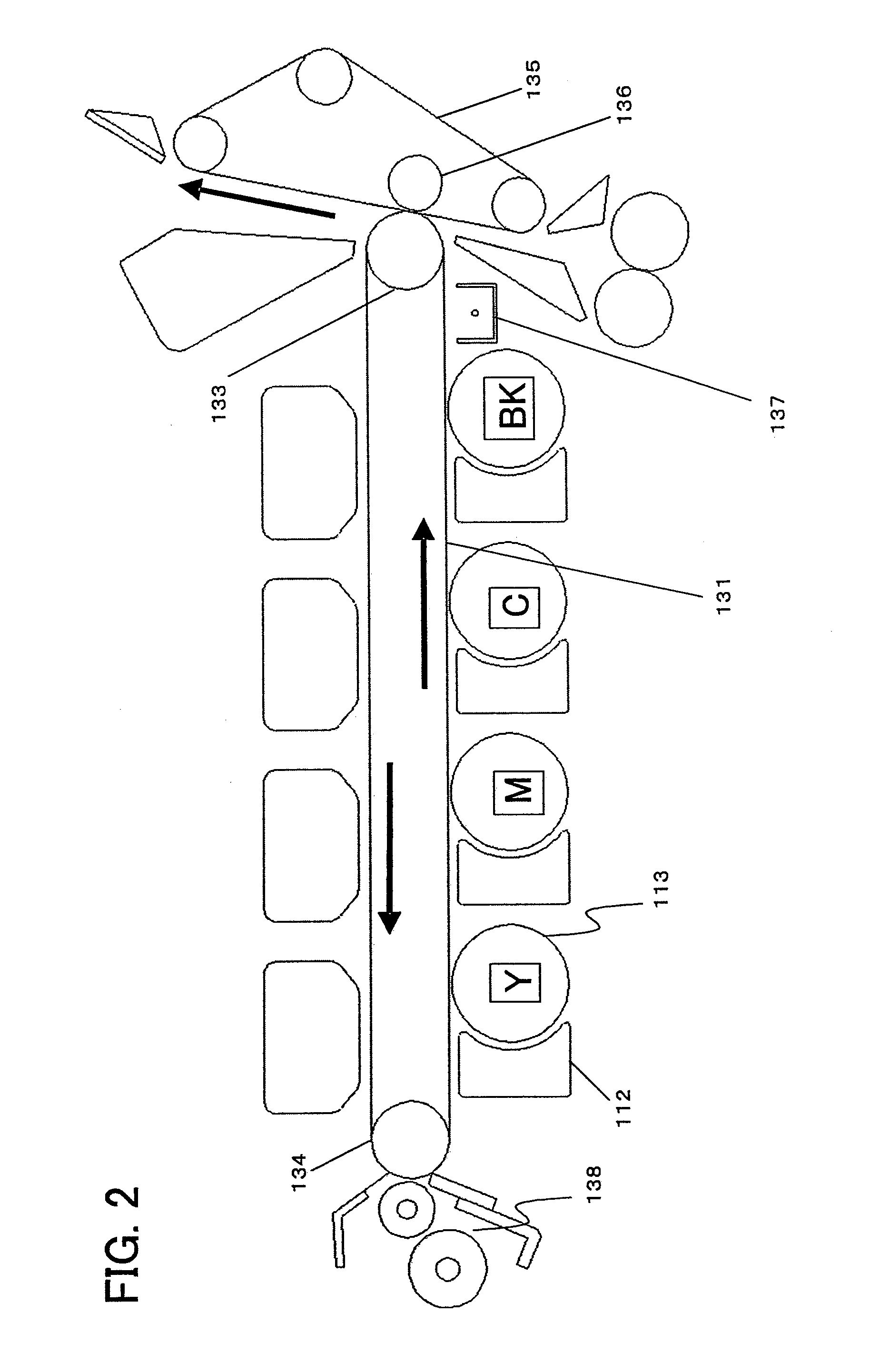
[0031]FIG. 1 is a view showing a configurational example of an image forming apparatus including a transfer device according to the present invention. FIG. 2 is a view showing a configurational example of a transfer device with its peripheral devices according to the present invent...


PUM


Abstract

A transfer device includes a transfer device controller for controlling the whole transfer device, a storage for storing various kinds of data etc. necessary for control, an intermediate transfer unit including a primary transfer power supply and its driver, a secondary transfer unit including a secondary transfer power supply and its driver, and a PTC unit. In the transfer device, a controller communicates with a main controller that controls the whole image forming apparatus, and acquires, for example, information on the total print count or the like. When PTC radiation is determined to be needed based on the above information, the controller controls to drive the PTC unit.

Description

[0001]This Nonprovisional application claims priority under 35 U.S.C. §119(a) on Patent Application No. 2008-026275 filed in Japan on 6 Feb. 2008, the entire contents of which are hereby incorporated by reference.BACKGROUND OF THE INVENTION[0002](1) Field of the Invention[0003]The present invention relates to a transfer device that performs electrical cleaning as well as to an image forming apparatus using this transfer device.[0004](2) Description of the Related Art[0005]Conventionally, color image forming apparatuses such as copiers, printers, facsimile machines and the like, include a transfer device for transferring a color toner image formed by the image forming portions, to recording paper. As one of known transfer mechanisms of such a transfer device there is an intermediate transfer system in which toner images of different colors formed at the image forming units corresponding to each color are successively transferred to an intermediate transfer element or a belt so that e...

Claims


Application Information

Patent Timeline
Patent Type & Authority Patents(United States)
IPC IPC(8): G03G21/00G03G15/16
CPCG03G15/161G03G15/0131G03G2215/00059
Inventor TAKIGUCHI, TOSHIKIIZUMI, HIDESHIYOSHIDA, TAKAHIKOMURAI, HIROYUKI
Owner SHARP KK
Why Eureka
Try Eureka