Built-in cooking appliance and installation apparatus for the same

a technology for installing apparatuses and cooking appliances, which is applied in the direction of lighting and heating apparatus, domestic stoves or ranges, heating types, etc., can solve the problems of short circuit or malfunction of cooking appliances, difficult cleaning of the top plate proportion, and difficulty in cleaning the top plate, etc., to achieve convenient cleaning, convenient cleaning, and cooling efficiency of built-in cooking appliances.

Active Publication Date: 2010-05-06
LG ELECTRONICS INC
View PDF8 Cites 4 Cited by
  • Summary
  • Abstract
  • Description
  • Claims
  • Application Information

AI Technical Summary

Benefits of technology

[0012]According to an embodiment, cooling efficiency of a built-in cooking appliance, stability in using, convenience in cleaning, esthetic feeling, and high reliability of a product can be obtained.

Problems solved by technology

Accordingly, a portion around the top plate is difficult to clean, and an appearance is not elegant.
The water flowing into the main body of the cooking appliance may cause a short circuit or malfunction of the cooking appliance.
This limitation must be considered in designing the cooking appliance as the cooking appliance is used in the kitchen that is in a most wet environment.

Method used


Image

  • Built-in cooking appliance and installation apparatus for the same
  • Built-in cooking appliance and installation apparatus for the same
  • Built-in cooking appliance and installation apparatus for the same

Examples


first embodiment

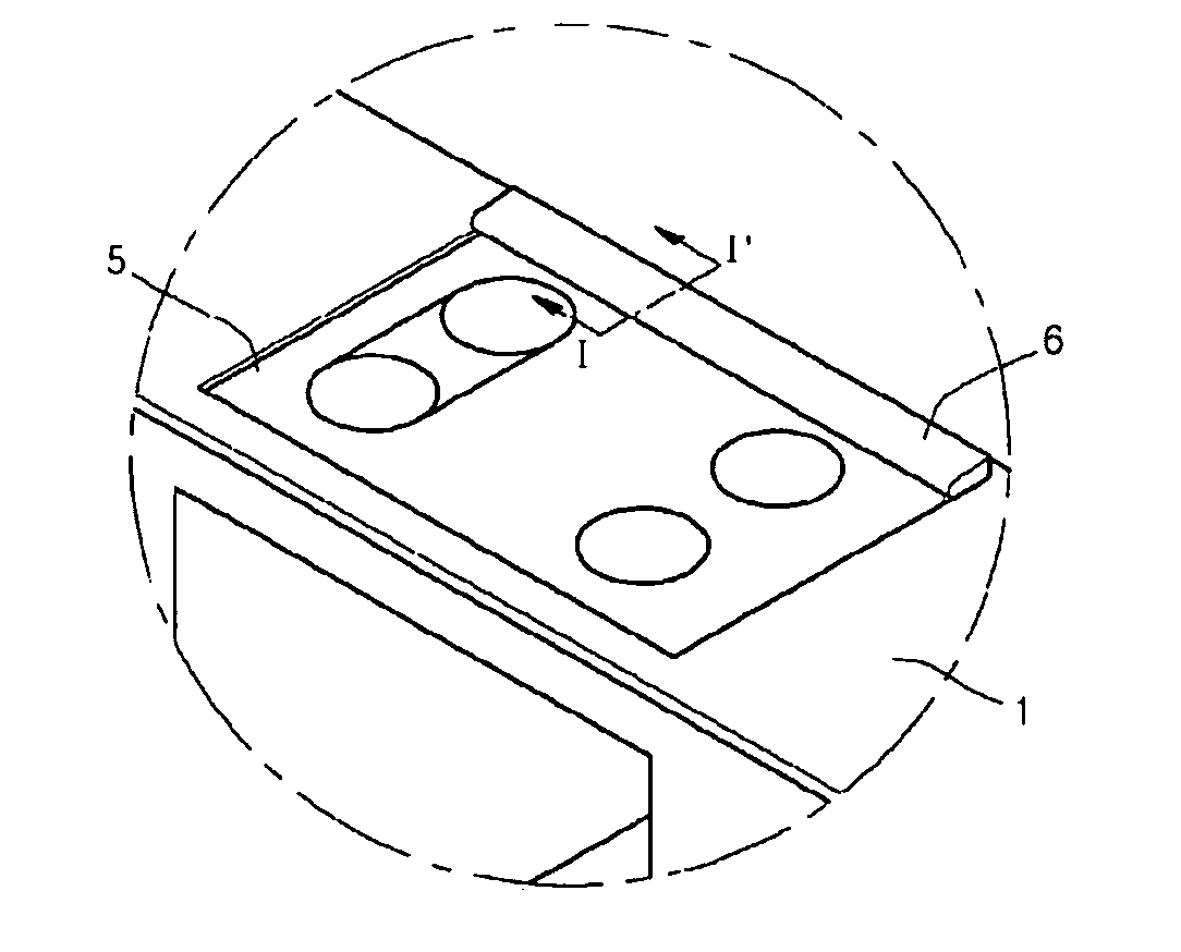
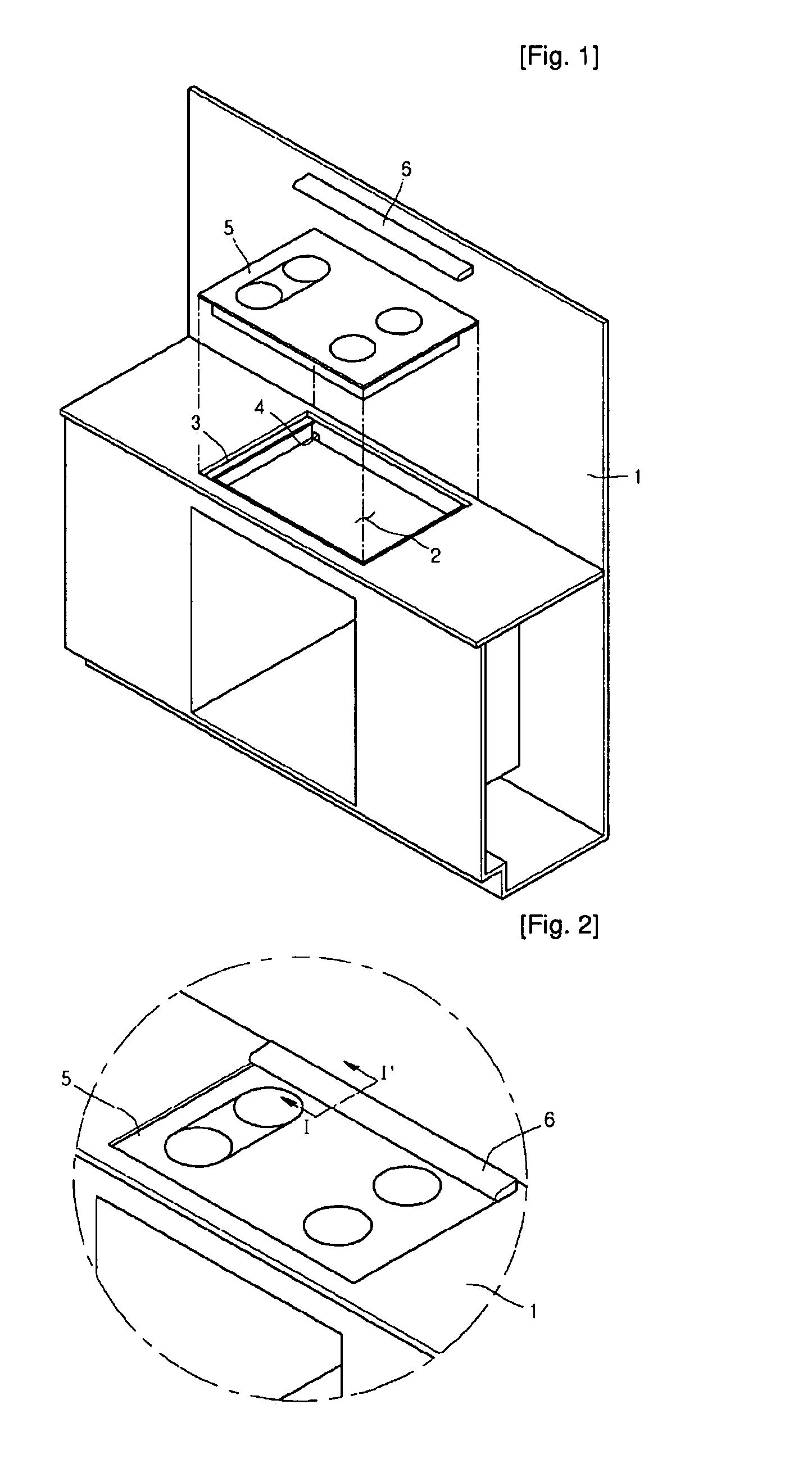
[0024]FIG. 1 is a perspective view illustrating a built-in cooking appliance installed according to an embodiment.

[0025]Referring to FIG. 1, the built-in cooking appliance includes a cabinet 1, a depressed portion 2 recessed downward from one side of the cabinet 1 to provide a space on which a cooking appliance is disposed, a seat portion 3 recessed downward from the edges of the depressed portion 2 and provided to have a height difference, a cooking appliance 5 seated on the seat portion 3, a water outlet 4 formed by opening one side of the depressed portion 2, and a top frame 6 covering a portion separated between the cooking appliance 5 and the cabinet 1 at the upper side.

[0026]The seat portion 3 is a portion recessed downward by a predetermined distance from the edges of the depressed portion 2. The seat portion 3 supports the edges of the cooking appliance 5. In detail, the seat portion 3 supports a high temperature top plate 51 of FIG. 3 provided to the upper end of the cookin...

second embodiment

[0070]FIG. 6 is a partially cut perspective view of a built-in cooking appliance according to another embodiment, and FIG. 7 is a cross-sectional view taken along the line of FIG. 6.

[0071]Referring to FIGS. 6 and 7, a top plate 200 directly / indirectly supporting a case containing food while forming an upper appearance is provided to the upper end of the cooking appliance. An inner space is formed under the top plate 200 to receive a main body 300 on which a plurality of parts are mounted. The top plate 200 and the main body 300 form an appearance of a cooking appliance.

[0072]The top plate 200 is formed in a quadrangular plate having a predetermined thickness using heat tempered glass made of ceramic material to have a property strong against heat. The top plate is for enduring heat generated from a heat source mounted in the inner space of the main body 300 and cooking food.

[0073]The top plate 200 is supported by a seat, which is a portion formed by recessing the edges of a receivin...


PUM


Abstract

Provided is a built-in cooking appliance. According to the built-in cooking appliance, the inside of the cooking appliance is effectively cooled and the inside can be waterproofed without protruding the top plate above the cabinet. Therefore, cooling efficiency, stability in using, convenience in cleaning, esthetic feeling, and reliability of a product can be improved. The built-in cooking appliance includes a top plate, a main body below the top plate, a fan, a cabinet, a gap portion, and a top frame. At least a heating unit is disposed inside the main body. The fan forms a cooling passage inside the main body. The plate is installed on the cabinet. The gap portion defines at least a portion of the cooling passage, and is formed by at least an edge on one side of the top plate and the cabinet separated from each other. The top frame covers the gap portion.

Description

TECHNICAL FIELD[0001]The present disclosure relates to a built-in cooking appliance and an installation apparatus thereof, and more particularly, to a cooking appliance having a high temperature top plate to cook food.BACKGROUND ART[0002]A built-in cooking appliance is a kitchen appliance directly installed on a cabinet. That is, the built-in cooking appliance is installed when a furniture such as a cabinet is installed in the kitchen, so that a user can conveniently use the same. The built-in cooking appliance makes the interior of the kitchen beautiful.[0003]In recent years, a built-in cooking appliance having a top plate, which can cook the food using heat transmitted to the food through the top plate, has been developed. Such a built-in cooking appliance having the top plate is called a hot plate, a hob, a range, or a cook-top. Regardless of the name, a concept of the present invention may be applied to any cooking appliances having the top plate. In the following description, a...

Claims


Application Information

Patent Timeline
Patent Type & Authority Applications(United States)
IPC IPC(8): H05B3/68F28D15/00
CPCF24C15/101H05B6/1263
Inventor YI, SOO CHEOLLEE, WANG LIM
Owner LG ELECTRONICS INC
Why Eureka
Try Eureka