

Bio signal measuring apparatus and method
a signal measuring and signal technology, applied in the field of bio signal measuring apparatus and method, can solve the problem that the peak cannot be accurately detected
- Summary
- Abstract
- Description
- Claims
- Application Information
AI Technical Summary
Benefits of technology
Problems solved by technology
Method used
Image

Examples
Embodiment Construction
[0021]The present invention will now be described more fully with reference to the accompanying drawings, in which exemplary embodiments of the invention are shown.
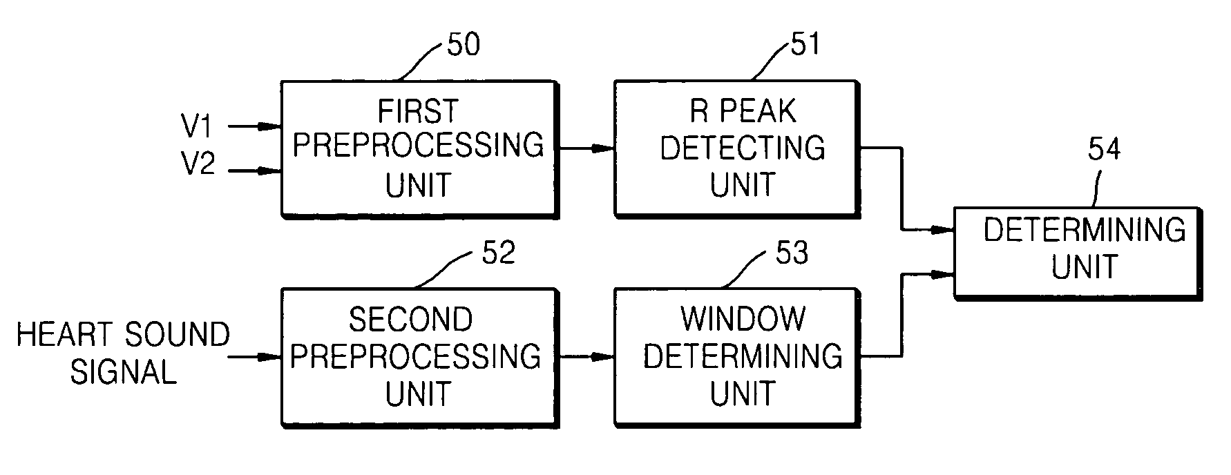
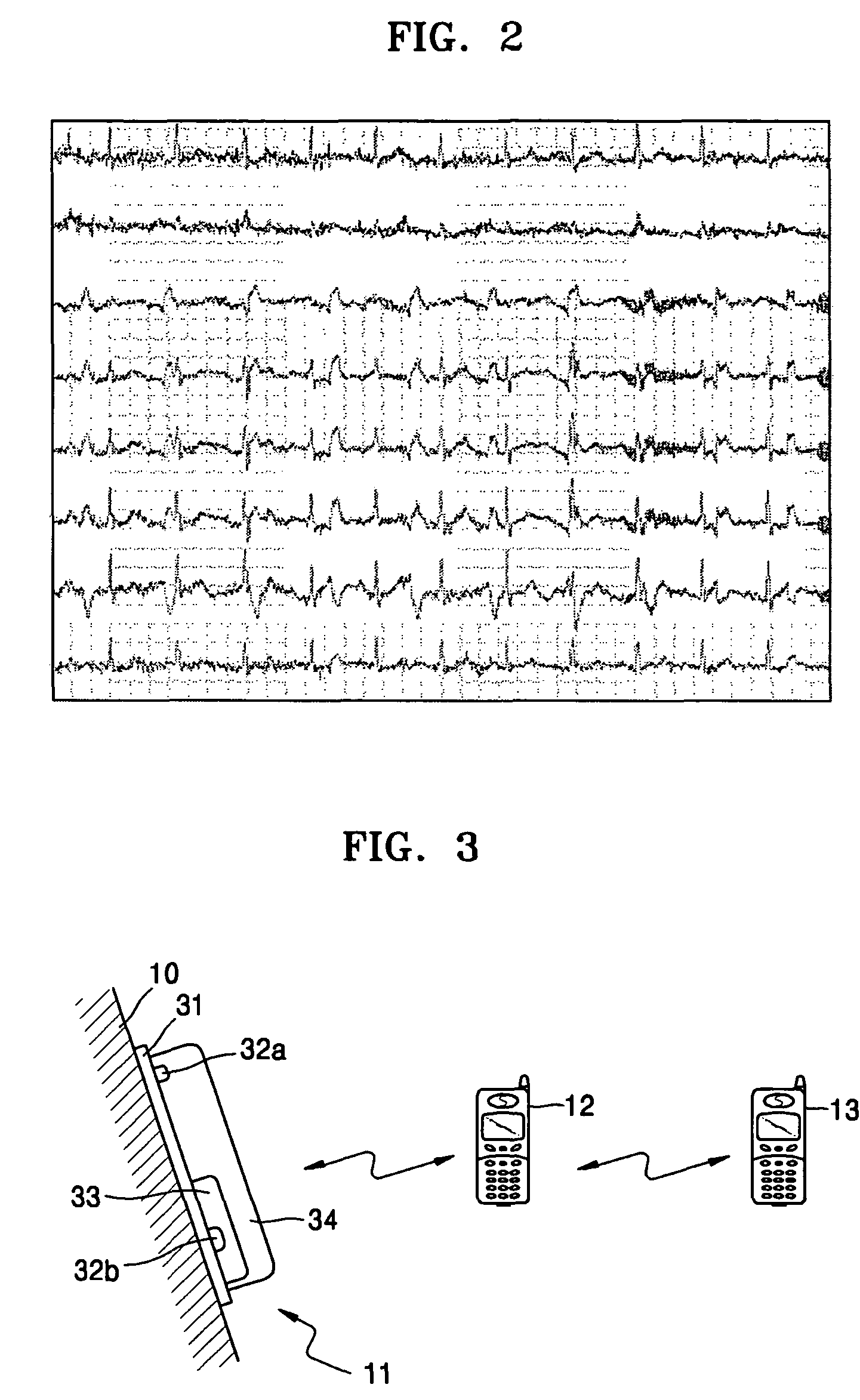
[0022]FIG. 3 shows a bio signal measuring apparatus according to the present invention. The bio signal measuring apparatus 11 is attached to the skin of a user, measures a bio signal of the user and transmits the bio signal and bio information obtained by processing the bio signal to a portable terminal 12. The bio information may be a heart rate or a heartbeat interval. The portable terminal 12 adequately process the bio signal to obtain the bio information and display the bio information to the user, when receiving the bio signal. In another example, the portable terminal 12 may display the received bio information to the user, when receiving the bio information. The bio signal or the bio information transmitted to the portable terminal 12 is provided to a server (not shown) and further provided to a portable terminal 1...
PUM
 Abstract
Description
Claims
Application Information