Roman shade

a shade and roman technology, applied in the field of roman shades, can solve the problems of increasing the number of manufacturing steps affecting and requiring a relatively large number of manufacturing steps to attach the upper end of the second fabric, so as to reduce the operation load upon lifting up/down the second fabric, increase the number of manufacturing steps, and reduce the appearance of the second fabri

Active Publication Date: 2011-04-26
TOSO COMPANY
View PDF42 Cites 16 Cited by
  • Summary
  • Abstract
  • Description
  • Claims
  • Application Information

AI Technical Summary

Benefits of technology

[0014]In the roman shade, the first lift cord suspended from the head rail is routed into the rear side of the first fabric, and the second lift cord, which is suspended from the head rail and lifts up / down the second fabric, is routed into the rear side of the second fabric so as to come over the upper end of the second fabric, such that the second lift cord is almost completely isolated from the first lift cord to thereby prevent the second cord from entangling with the first lift cord, and an appearance of the second fabric would not be degraded since the second lift cord hides behind the second fabric even when the first fabric is tucked up near to the head rail.
[0032]On the other hand, even in the cases that the upper end of the first fabric is attached to the front surface of the head rail, that the upper end of the second fabric is attached to the rear surface of the head rail, and that the second lift cord is pulled out into the rear side of the head rail so as to come over the upper end of the second fabric to be suspended into the rear side of the second fabric, the present roman shade does not require the insertion hole, having been required in the convention roman shade, for guiding the second lift cord to the rear side of the second fabric. Accordingly, the insertion hole is no longer necessary for the present roman shade, and therefore the number of manufacturing steps in forming the insertion hole, which has been necessitated for the second fabric in the conventional roman shade, can be omitted. In this case, if the head rail is configured to enclose the first lift cord or the front side cord roll-up drum, and the second lift cord or the rear side cord roll-up drum, a width of the head rail can be equalized to that of the head rail which encloses a single roll-up drum, resulting in preventing the amount of projection of the first fabric into the room from increasing. Also, if the head rail is configured such that the lower space sectioned by the partition encloses the first lift cord or the front side cord roll-up drum, and the upper space sectioned by the partition encloses the second lift cord or the rear side cord roll-up drum, a mutual cushioning can be prevented. Further, if the second lift cord pulled out into the rear side of the head rail from the upper space is provided with a guide member for guiding the second lift cord to the rear side of the second fabric, the guide member guides the second lift cord having been pulled out into the rear side of the head rail to the rear side of the second fabric, such that the second lift cord and the second fabric are prevented from causing an unnecessary friction resistance. Therefore, an operation load upon lifting up / down the second fabric can be reduced.

Problems solved by technology

However, in the roman shade disclosed in the above conventional JP '934 when only the first fabric is tucked up near to the head rail while the second fabric is down, the insertion hole formed near the upper end of the second fabric is exposed to an inside of the room, thereby causing a problem of degradedness of the appearance of the second fabric.
Also, in the roman shade as disclosed in the above conventional JP '934 since the insertion hole must be formed at a position of the second fabric so as to correspond to a suspended position of the second lift cord, there was a problem in increasing the number of manufacturing steps of the second fabric.
Namely, there is a problem of occurring a filtering of the light in the form of the spot light into the room.
On the other hand, in the roman shade as disclosed in the above conventional JP '934 the head rail is generally mounted horizontally onto a wall surface or a ceiling of the room at a position above an opening such as a window, such that, although it is relatively easy to attach the upper end of the first fabric onto the front surface of the head rail which is facing to the inside of the room, there is such a problem that it requires relatively large number of manufacturing steps to attach the upper end of the second fabric onto the rear surface of the head rail which is facing to the wall surface of the room because of a relatively small space between the rear surface of the head rail and the wall surface of the room.
However, mounting the head rail, on which the fabric has been preliminary attached, onto the wall surface or the like of the room involves remarkably lower workability in comparison with mounting the head rail without the fabric onto the wall surface or the like of the room.
As such, there still was a problem of cumbersome in exchanging the second fabric which is attached to the rear surface of the head rail because of a relatively small space between the rear surface of the head rail and the wall surface or the like of the room as having been described above, and thus it takes time to exchange the second fabric.

Method used


Image

  • Roman shade
  • Roman shade
  • Roman shade

Examples


Embodiment Construction

[0042]Now, an embodiment for carrying out the present invention will be described with reference to the accompanying drawings.

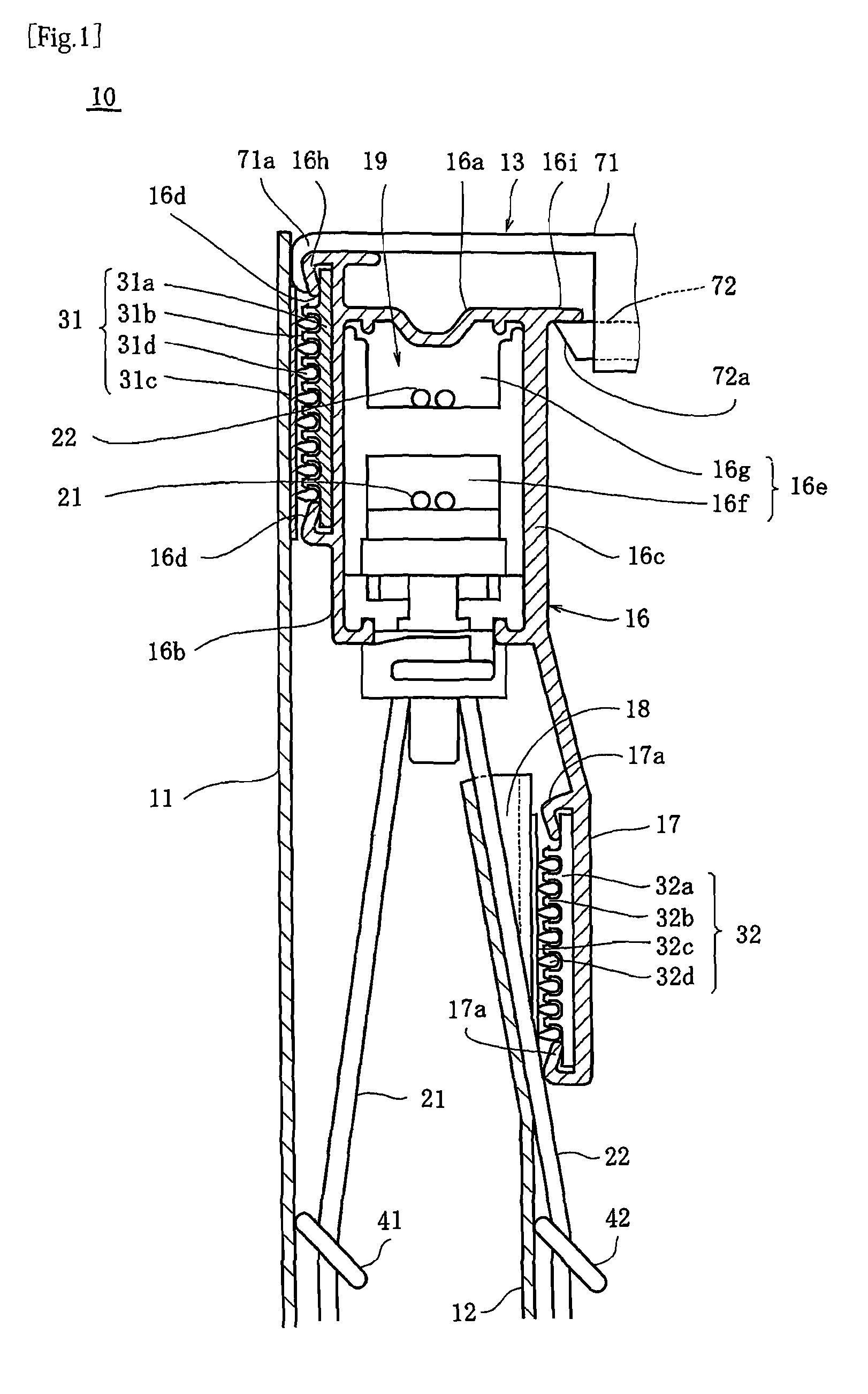
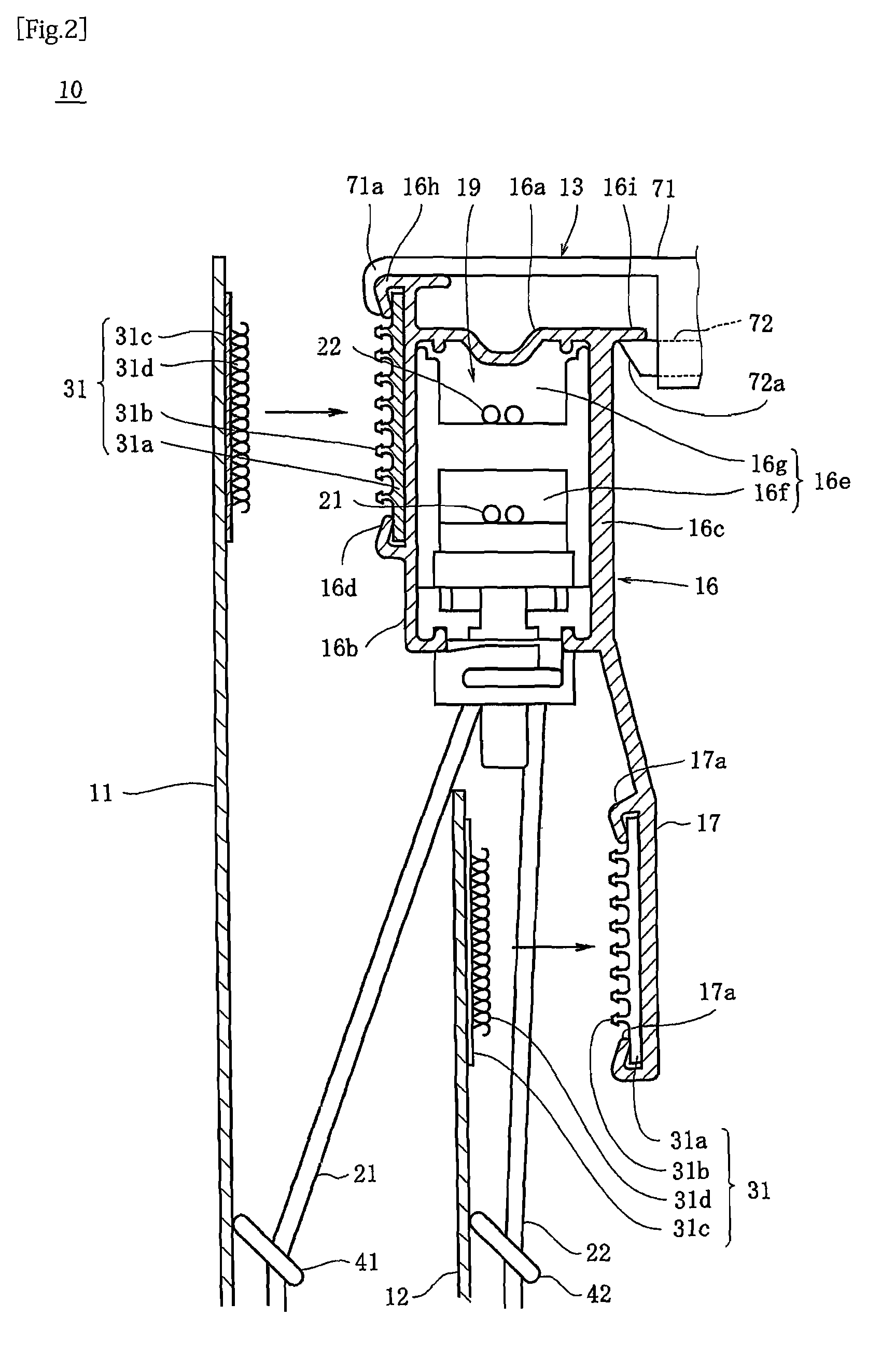
[0043]As shown in FIGS. 1 and 4, a roman shade 10 includes: a head rail 16 mounted onto a wall surface 14 of a room through a fixing bracket 13; a first fabric 11 and a second fabric 12 of which upper ends are attached to the head rail 16, respectively, and which have substantially the same length as that of the head rail 16; and a first lift cord 21 and a second lift cord 22 suspended from the head rail 16 in a liftable manner and coupled to the first fabric 11 and the second fabric 12, respectively. The head rail 16 is formed into a reverse U-shape in cross section by means of an extrusion molding or a pultrusion molding for metal such as an aluminum alloy, and has a top plate portion 16a, a front wall 16b suspended from a front edge of the top plate portion 16a, and a rear wall 16c suspended from a rear edge of the top plate portion 16a.

[0044]As shown in ...


PUM


Abstract

Upper ends of the first fabric and the second fabric are attached to the head rail, respectively, and the first lift cord and the second lift cord suspended from the head rail in a liftable manner are coupled to the first fabric and the second fabric, respectively. The first lift cord is routed into a rear side of the first fabric and the second lift cord is routed into a rear side of the second fabric so as to come over an upper end of the second fabric. An extension member is provided so as to extend downwardly along with a lower edge of a rear portion of the head rail, and the upper end of the second fabric is attached to a front surface of the extension member.

Description

CROSS REFERENCE TO RELATED APPLICATION[0001]This is a U.S. national phase application under 35 U.S.C. §371 of International Patent Application No. PCT / JP2007 / 053148 filed Feb. 21, 2007 and claims the benefit of Japanese Application No. 2006-064016 filed Mar. 9, 2006 and Japanese Application No. 2006 / 285973 filed Oct. 20, 2006, The International Application was published on Sep. 13, 2007 as International Publication No. WO / 2007 / 102314 under PCT Article 21(2) the contents of these applications are incorporated herein in their entirety.TECHNICAL FIELD[0002]The present invention relates to a roman shade for lifting up / down fabric of which upper ends are attached to a head rail, respectively.BACKGROUND OF ART[0003]Conventionally, a roman shade which is attached to an opening such as a window or the like of a house from an inside of the room has been known. The roman shade for lifting up / down a fabric of which upper end is attached to a head rail is configured such that the fabric covers ...

Claims


Application Information

Patent Timeline
Patent Type & Authority Patents(United States)
IPC IPC(8): A47H5/00E06B9/30A47H1/00E06B3/48
CPCE06B9/262E06B9/323A47H2201/02E06B2009/2625E06B9/32E06B2009/2622E06B2009/2452A47H5/02A47H11/00
Inventor HONDA, TOSHIMITSUMUTO, TOMONORISOMEYA, HIROYUKIMORI, TOSHIYUKI
Owner TOSO COMPANY
Why Eureka
Try Eureka