

Laminated coil
a technology of laminated coils and coils, applied in the direction of transformers/inductance details, basic electric elements, inductances, etc., can solve the problem of reducing the amount of magnetic flux blocked by increasing the conductor width of the coil, and achieve excellent dc superposition characteristics, reduce direct current resistance, and prevent the effect of inductance reduction
- Summary
- Abstract
- Description
- Claims
- Application Information
AI Technical Summary
Benefits of technology
Problems solved by technology
Method used
Image

Examples
first preferred embodiment
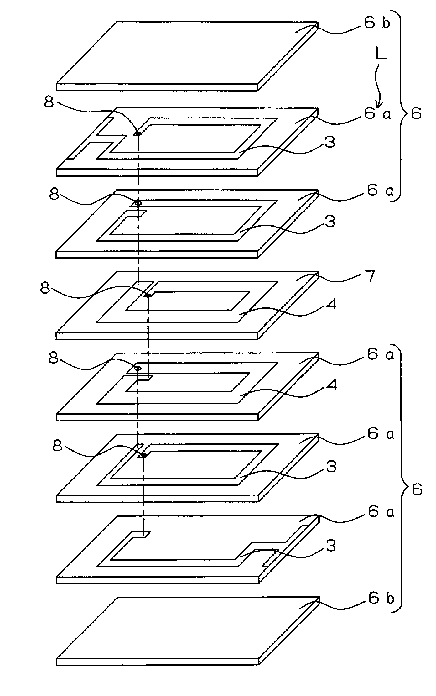
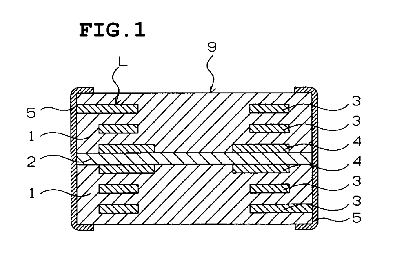
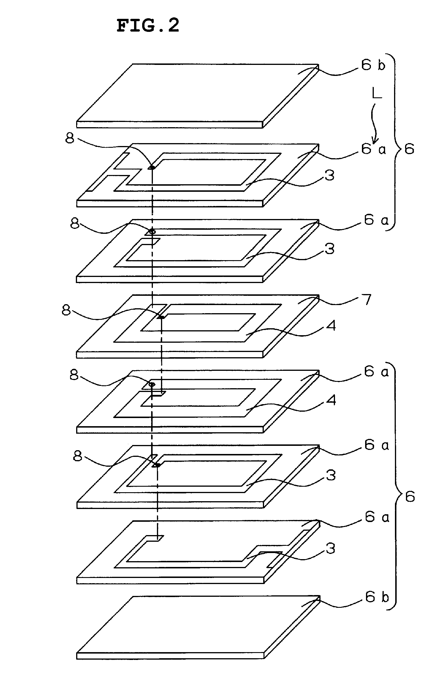
[0024]FIG. 1 is a schematic cross-sectional view of a laminated coil according to a first preferred embodiment of the present invention. The laminated coil includes a laminated body 9 having magnetic body sections 1 and a non-magnetic body section 2, a coil L including helically connected coil conductors 3 and 4 provided on the laminated body 9, and external electrodes 5. The magnetic body sections 1 are provided on both main surfaces of the non-magnetic body section 2. The magnetic body sections 1 each include a plurality of magnetic layers, and the non-magnetic body section 2 includes one non-magnetic layer.
[0025]As shown in FIG. 1, the coil conductors 4 are provided on both main surface of the non-magnetic body section 2. The conductor width of the coil conductors 4 is greater than that of the other coil conductors 3 having a predetermined conductor width. Since the conductor width of the coil conductor 4 is increased, the direct current resistance of the laminated coil is reduce...
second preferred embodiment
[0039]The structure of a laminated coil according to a second preferred embodiment of the present invention preferably is substantially the same as the structure of the laminated coil according to the first preferred embodiment illustrated in FIG. 1. However, for a laminated coil according to the second preferred embodiment, the conductor width of the coil conductors 4 disposed on both main surfaces of the non-magnetic body section 2 is about 750 μm, and the conductor width of the coil conductors 3 that are not disposed on both main surfaces of the non-magnetic body section 2 is about 350 μm. The conventional example shown in Table 3 below represents a laminated coil whose coil conductors 13 provided on magnetic body sections 11 and a non-magnetic body section 12 all have a conductor width of about 350 μm, as shown in FIG. 3. The second comparative example, as shown in FIG. 8, represents a laminated coil whose coil conductors 34 that are not provided on both main surfaces of a non-m...
third preferred embodiment
[0041]FIG. 5 illustrates a schematic cross-sectional view of a laminated coil according to a third preferred embodiment of the present invention. In FIG. 5, the components that are the same as or correspond to those in FIG. 1 are represented by the same reference numeral as those in FIG. 1, and descriptions thereof are not repeated.
[0042]In the laminated coil according to the third preferred embodiment, the coil conductors 4 are provided inside the non-magnetic body section 2. The conductor width of the coil conductors 4 is greater than the conductor width of the other coil conductors 3. Similar to the first preferred embodiment, the laminated coil according to the third preferred embodiment is produced through steps of stacking and pressure bonding green sheets having coil conductors, cutting the green sheets into chips, and forming external electrodes.
[0043]By providing the coil conductors 4 having an increased conductor width, the direct current resistance is reduced. Furthermore...
PUM
 Abstract
Description
Claims
Application Information