Laminated coil

A stacked coil technology, applied in coil manufacturing, transformer/inductor coil/winding/connection, inductor, etc., can solve the problem of the overall shape of the laminated body becoming larger, so as to improve coil characteristics, reduce DC resistance, Effect of Improving DC Superposition Characteristics

Inactive Publication Date: 2012-04-04
MURATA MFG CO LTD
View PDF4 Cites 11 Cited by
  • Summary
  • Abstract
  • Description
  • Claims
  • Application Information

AI Technical Summary

Problems solved by technology

[0007] However, in the laminated coil, if the coil pattern is enlarged, there is a problem that the overall shape of the laminated body becomes larger.

Method used


Image

  • Laminated coil
  • Laminated coil
  • Laminated coil

Examples


Embodiment approach

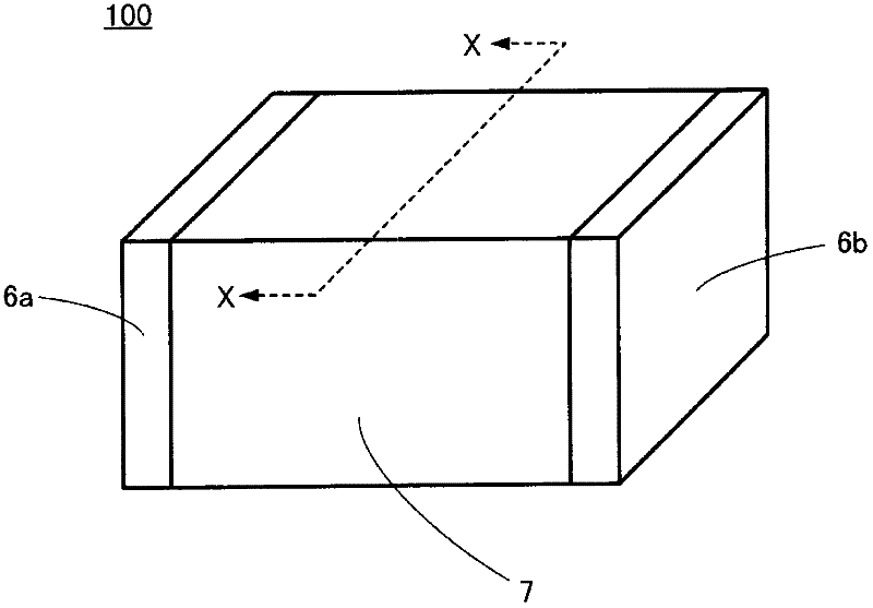
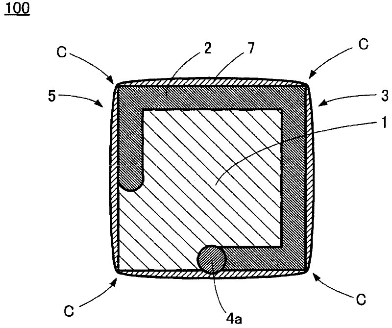
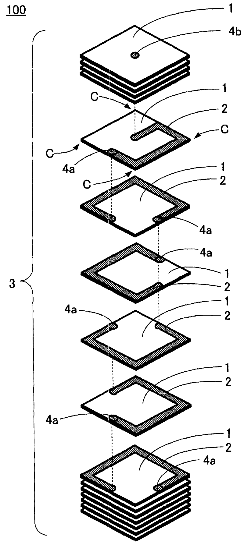
[0053] Figure 1 ~ Figure 3 A laminated coil 100 according to an embodiment of the present invention is shown. in, figure 1 is a stereogram, figure 2 yes figure 1 Cross-sectional view of the dotted line X-X part, image 3 It is an exploded perspective view. In addition, in image 3 In , illustration of the external electrodes 6a, 6b and the insulating film 7 is omitted.

[0054] Such as Figure 1~3 As shown, in the laminated coil 100 , a rectangular insulating layer 1 having four corners C and a coil pattern 2 are laminated and integrated to form a laminated body 3 . The size of the laminated body 3 is arbitrary, for example, it is 0.6 mm in the vertical direction, 1.0 mm in the horizontal direction, and 1.9 mm in length.

[0055] For the insulating layer 1 , a magnetic material such as ferrite or a nonmagnetic material such as dielectric ceramic is used. When a magnetic material is used for the insulating layer 1, the laminated coil 100 is a magnetic core type. W...


PUM


Abstract

The present invention relates to a laminated coil, and more specifically to a laminated coil in which the diameters of coil patterns are increased and an insulating film is formed on the outer peripheral surface of a laminate. A laminated coil (100) includes a laminate (3) having substantially rectangular insulating layers (1) and coil patterns (2) that are alternately laminated and unified, through holes (4a), a coil (5) formed inside the laminate (3) from the coil patterns (2) connected to each other via the through holes (4a), external electrodes (6a, 6b), and an insulating film (7) formed on the outer peripheral surface of the laminate (3). At least one of the through holes (4a) is partially exposed in the surface of the laminate (3) and is formed in contact with one side of the outer edge of the insulating layer (1) but out of contact with the other sides other than the one side.

Description

technical field [0001] The present invention relates to a laminated coil, and more specifically, to a laminated coil in which the diameter of a coil pattern is increased and an insulating film is formed on the outer peripheral surface of a laminated body. Background technique [0002] In recent years, in the electrical and electronic fields, laminated coils capable of miniaturization and excellent in mass productivity have been widely used. In this laminated coil, a plurality of insulating layers and a plurality of coil patterns are sequentially laminated in a desired order and integrated, and the coil patterns are sequentially connected through via holes to form a coil inside the laminated body. Usually, the outer peripheral edge of the coil pattern is formed inside the outer peripheral edge of the insulating layer, and a space is provided so that the outer peripheral edge of the coil pattern is not exposed on the outer peripheral surface of the laminated body. In addition...

Claims


Application Information

Patent Timeline
Patent Type & Authority Applications(China)
IPC IPC(8): H01F17/00H01F27/32H01F41/12
CPCH01F27/32H01F17/00H01F27/02H01F41/12H01F27/292H01F17/0013H01F27/28
Inventor 桥本大喜
Owner MURATA MFG CO LTD
Why Eureka
Try Eureka