AI technical title is built by Patsnap AI team. It summarizes the technical point description of the patent document.
A technology of stacking coils and components, applied in transformer/inductor components, electrical components, transformer/inductor coils/windings/connections, etc., can solve problems such as inductance reduction and inability to obtain DC superposition characteristics
Active Publication Date: 2014-02-19
MURATA MFG CO LTD
View PDF9 Cites 11 Cited by
Summary
Abstract
Description
Claims
Application Information
AI Technical Summary
This helps you quickly interpret patents by identifying the three key elements:
Problems solved by technology
Method used
Benefits of technology
Problems solved by technology
[0009] However, laminated coil components such as laminated inductors form a closed magnetic circuit, so magnetic saturation tends to occur when a large current is applied, and the inductance decreases, so that the expected DC superposition characteristics cannot be obtained.
Method used
Image
Click on the blue label to locate the original text in one second.
Reading with bidirectional positioning of images and text.
[0101] As a ferrite raw material, prepare Fe 2 o 3 , Mn 2 o 3 , ZnO, NiO, and CuO, according to the composition of Table 1, weigh these ceramic raw materials. That is, take Fe 2 o 3 : 46.5mol%, Mn 2 o 3 : 2.5mol%, ZnO: 30.0mol%, CuO varies from 0.0 to 8.0mol%, and the rest is adjusted by NiO.
[0102] [Table 1]
[0103]
[0104] Next, these weighed objects were put into a ball mill made of vinyl chloride together with pure water and PSZ balls, thoroughly mixed and pulverized by a wet method, evaporated and dried, and then calcined at a temperature of 850°C.
[0106] Next, the slurry was shaped into a sheet with a thickness of 25 μm using a doctor blade metho...
Embodiment 2
[0139] Fe ready to form the main component of the ferrite material 2 o 3 , Mn 2 o 3 , ZnO, NiO, and CuO, and SnO as a subcomponent material 2 . Then Fe 2 o 3 : 46.5mol%, Mn 2 o 3 : 2.5mol%, ZnO: 30.0mol%, CuO: 1.0mol%, and NiO: 20.0mol% were weighed, and SnO was further weighed at 0.0 to 3.0 parts by weight relative to 100 parts by weight of the main component. 2 .
[0140] Except for this, the samples of sample numbers 11-14 were produced according to the method and procedure similar to Example 1.
[0141] Next, for each of the samples of sample numbers 11 to 14, the content weight and average crystal grain size of CuO were measured, and a thermal shock test and a DC superposition test were performed.
[0142] Table 3 shows the measurement results of each sample of sample numbers 11-14.
[0143] [table 3]
[0144]
[0145] It is obvious from sample numbers 11 to 14 that there is basically no difference in the inductance change rate ΔL in the thermal shock test,...
PUM
Abstract
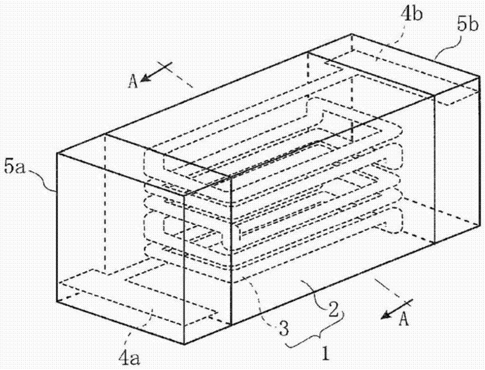
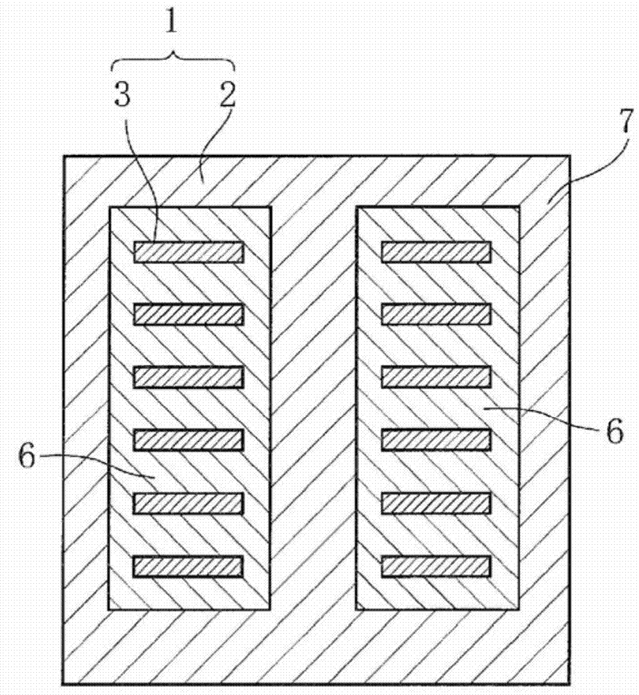
This multilayer coil part has a magnetic body section (2) that is made of an Ni-Zn system ferrite material and a Cu-based coil conductor (3) that has been wound into a coil shape. The coil conductor (3) is buried inside the magnetic body section (2) to form a part element body (1). The part element body (1) is divided into a first region (6) that is located close to the coil conductor (3) and a second region (7) that comprises the region other than the first region (6). The grain size ratio (D1 / D2) between the average crystal grain size (D1) of the magnetic body section (2) in the first region (6) and the average crystal grain size (D2) of the magnetic body section (2) in the second region (7) is equal to or lower than 0.85. The molar quantity of CuO content in the ferrite material is set to 6 mol% or less, and the ferrite material is baked in a reductive atmosphere with the oxygenpartial pressure being equal to or lower than the Cu-Cu2O equilibrium oxygenpartial pressure. Thus, a multilayer coil part that exhibits not only little fluctuation of inductance and excellent thermal shock resistance when subjected to a thermal shock or an external stress but also excellent direct-current superposition characteristics can be obtained without requiring any complicated step.
Description
technical field [0001] The present invention relates to a laminated coil component, and more specifically, to a laminated coil component such as a laminated inductor having a magnet portion made of a ferrite material and a coil conductor mainly composed of Cu. Background technique [0002] Conventionally, laminated coil components using ferrite magnets such as Ni—Zn having a spinelcrystal structure have been widely used, and development of ferrite materials has also been actively carried out. [0003] Such a laminated coil component has a structure in which a conductor part wound in a coil shape is embedded in a magnet part, and usually the conductor part and the magnet part are formed by simultaneous firing. [0004] However, in the above-mentioned laminated coil component, the linear expansion coefficient is different between the magnet portion made of ferrite material and the conductor portion mainly composed of conductive material. Stress deformation occurs inside duri...
Claims
Application Information
Patent Timeline
Application Date:The date an application was filed.
Publication Date:The date a patent or application was officially published.
First Publication Date:The earliest publication date of a patent with the same application number.
Issue Date:Publication date of the patent grant document.
PCT Entry Date:The Entry date of PCT National Phase.
Estimated Expiry Date:The statutory expiry date of a patent right according to the Patent Law, and it is the longest term of protection that the patent right can achieve without the termination of the patent right due to other reasons(Term extension factor has been taken into account ).
Invalid Date:Actual expiry date is based on effective date or publication date of legal transaction data of invalid patent.

