Dynamic pressure bearing device

a bearing device and dynamic pressure technology, applied in the direction of sliding contact bearings, instruments, record information storage, etc., can solve the problems of poor rotation, unbalanced axial groove shape (groove length) of dynamic pressure generating grooves provided on radial bearing parts rb, and no thrust levitation in thrust bearing parts sb. , to achieve the effect of reducing unbalance, easy forming and smooth operation

Active Publication Date: 2005-09-06
NIPPON DENSAN CORP
View PDF7 Cites 28 Cited by
  • Summary
  • Abstract
  • Description
  • Claims
  • Application Information

AI Technical Summary

Benefits of technology

[0013]In order to achieve the above advantage, according to the present invention, there is provided a dynamic pressure bearing device including a bypass passage for pressure release for communicating between a space, which is positioned between one of two radial dynamic pressure bearing parts and a thrust dynamic pressure bearing part, and a space positioned outer side in the axial direction of the other radial bearing part. The bypass passage for pressure release is separately formed from the bearing space including two radial dynamic pressure bearing parts and a thrust dynamic pressure bearing part.
[0014]According to the dynamic pressure bearing device having such a constitution, even though, for example, the groove shape (groove length) of the dynamic pressure generating grooves provided on the radial bearing parts is formed in an unbalanced state, the lubricating fluid corresponding to the amount of the unbalance, caused by the unbalance of the pumping effect forces, flows from a high-pressure side to a low-pressure side through the bypass passage for pressure release to reduce the unbalance. Accordingly, the unbalanced state in the radial bearing part does not affect the thrust bearing part and the variation of the elevated amount in the thrust direction in the thrust bearing part is prevented.
[0015]In the dynamic pressure bearing device in accordance with the embodiment of the present invention, the bypass pass...

Problems solved by technology

In such dynamic pressure bearing devices, the groove shape (groove length) of the dynamic pressure generating grooves provided on the radial bearing part RB sometimes becomes unbalanced in the axial direction due to processing errors at the time of manufacturing.
The variation of the levitated amount in the thrust direction due to the unbalance in the radial bearing part RB has caused a significant pro...

Method used


Image

  • Dynamic pressure bearing device
  • Dynamic pressure bearing device
  • Dynamic pressure bearing device

Examples


Embodiment Construction

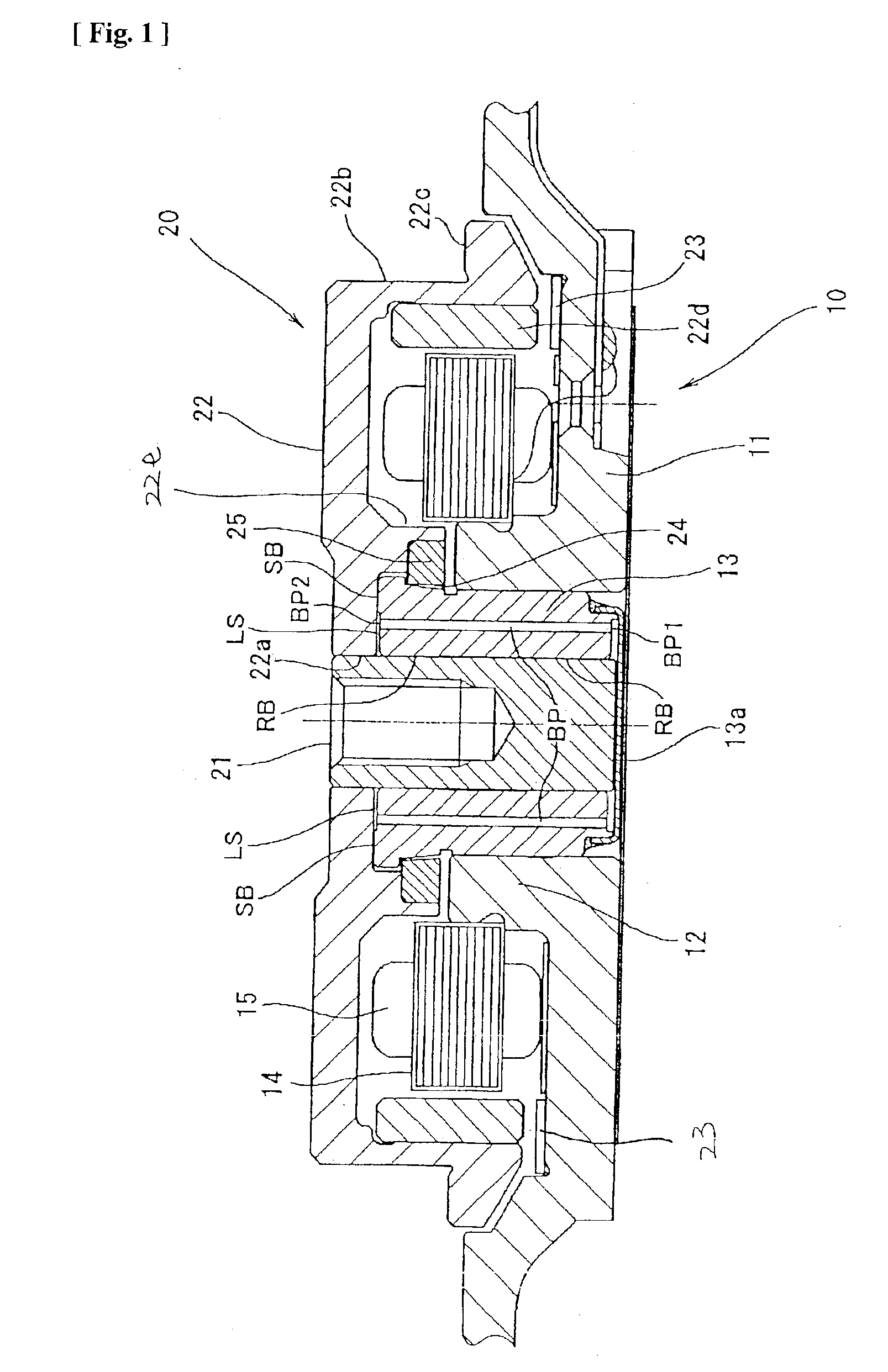
[0027]Preferred embodiments of the present invention will be described in detail below with reference to the accompanying drawings. A description will be made first as to an overview of a hard disk drive device (HDD) as an example to which a dynamic pressure bearing device according to the present invention is applied.

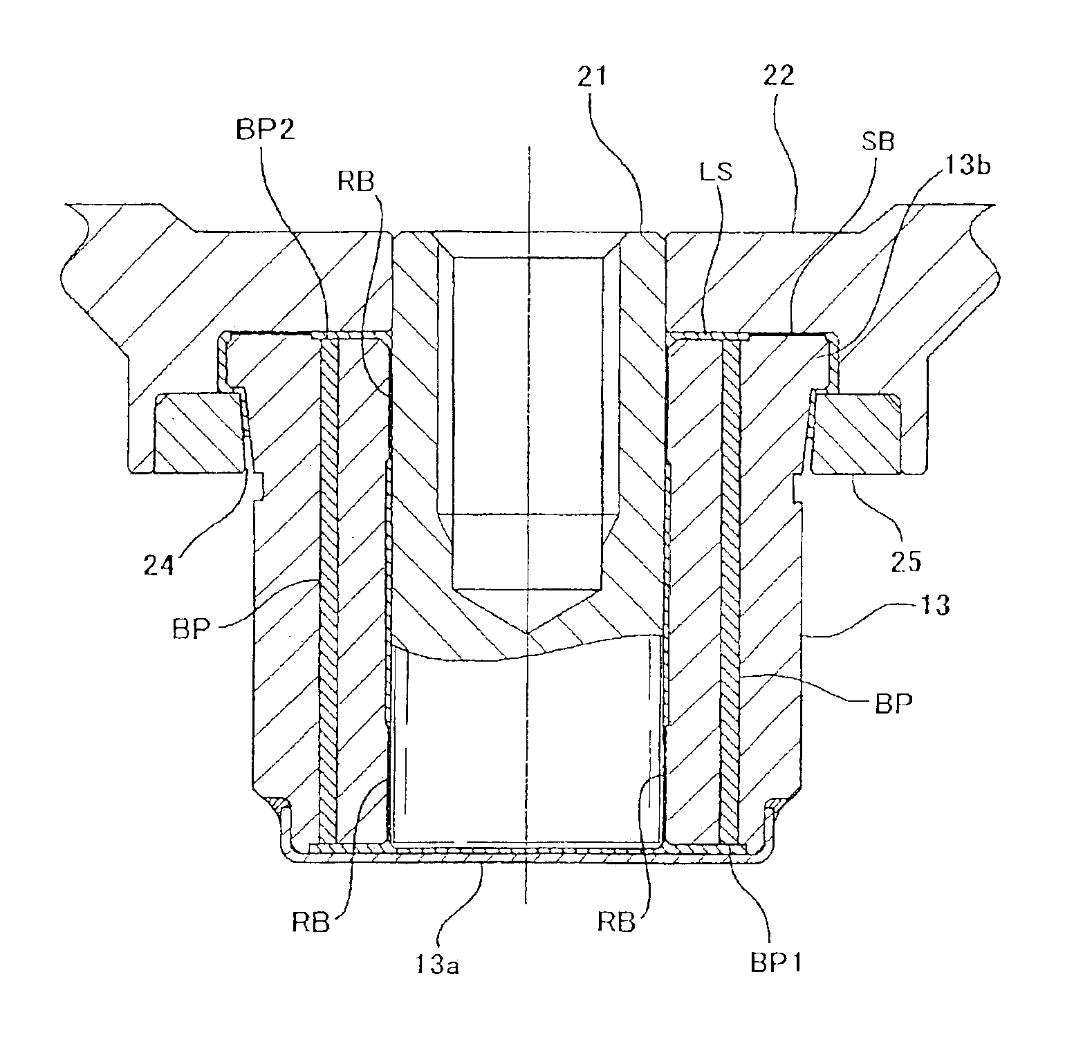
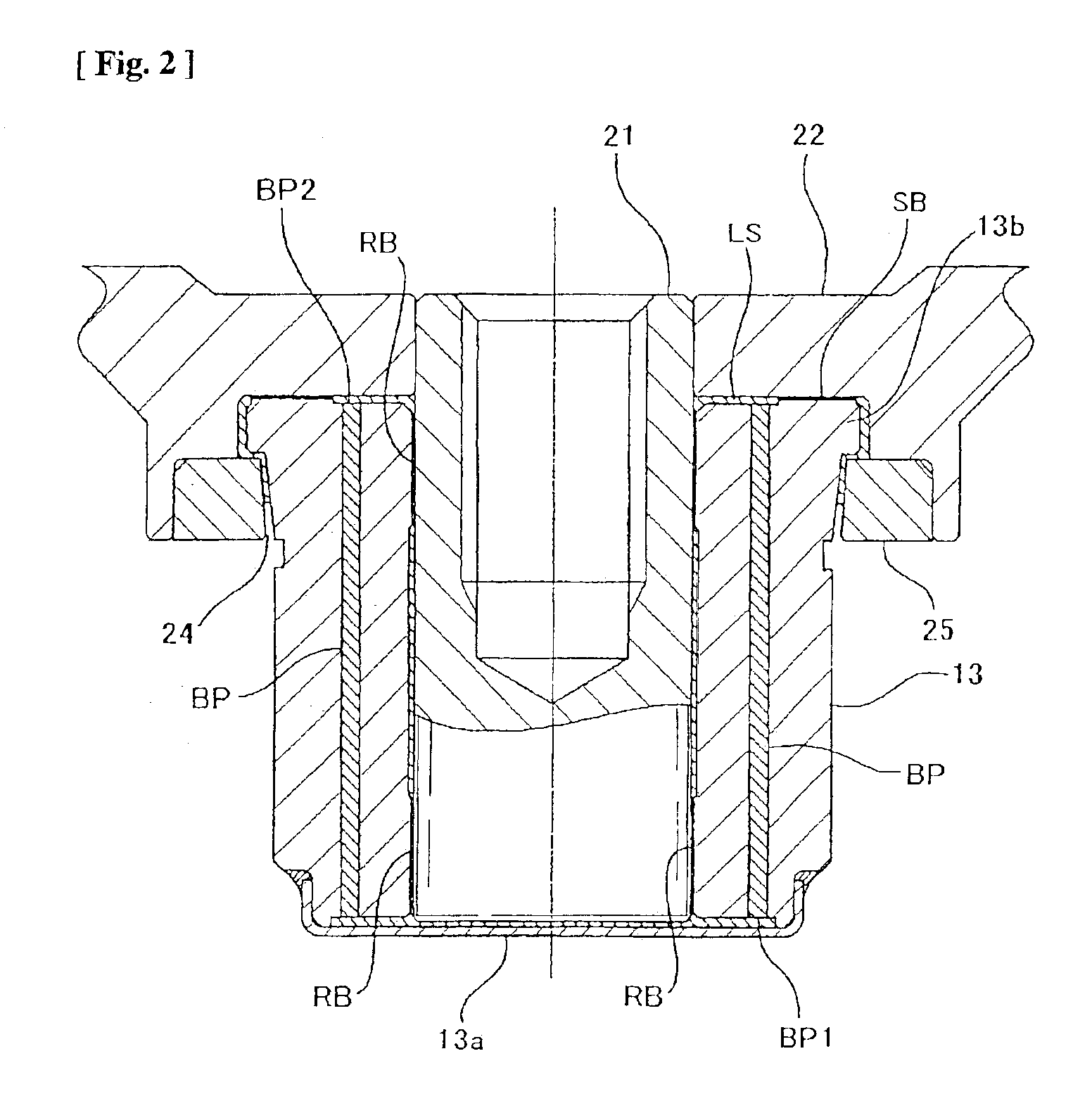
[0028]The overall view of a shaft rotation type HDD device shown in FIG. 1 includes a stator assembly 10, which is a fixed member, and a rotor assembly 20, which is a rotary member assembled onto the top of the stator assembly 10. The stator assembly 10 has a fixed frame 11, which is screwed to a fixed base omitted from drawings. The fixed frame 11 may be formed from an aluminum material to achieve a lighter weight. On the inner peripheral surface of a ring-shaped bearing holder 12 formed upright in the generally center part of the fixed frame 11 is a bearing sleeve 13, which is a fixed dynamic pressure bearing member formed in the shape of a hollow cylinder and joined...


PUM


Abstract

A dynamic pressure bearing device includes a rotary shaft, a dynamic pressure bearing member for supporting the rotary shaft, two radial dynamic pressure bearing parts and a thrust dynamic pressure bearing part formed between the dynamic pressure bearing member and the rotary shaft, and a lubricating fluid continuously filled in the two radial bearing parts and the thrust bearing part. A bypass passage for pressure release is provided for communicating across the two radial dynamic pressure bearing parts to flow the lubricating fluid corresponding to the amount of the unbalance caused by the unbalance of the pumping effect forces from a high-pressure side to a low-pressure side through the bypass passage to reduce the unbalance.

Description

BACKGROUND OF THE INVENTION[0001]1. Field of the Invention[0002]The present invention relates to a dynamic pressure bearing device in which one of a shaft and a bearing member is rotatably supported by the other with dynamic pressure generated by lubricating fluid.[0003]2. Description of Related Art[0004]In recent years, a dynamic pressure bearing device, in which a rotary shaft is supported by a dynamic pressure generated in a lubricating fluid, has been developed as a bearing device that can rotate a rotary body at a high speed and high accuracy for various kinds of rotational driving devices. In such a dynamic pressure bearing device, a bearing having a thrust bearing part SB structured as shown in FIG. 4, for example, has been proposed in order to make the entire device thinner. In the thrust bearing part SB, a rotary member (rotary hub) 3 is attached to a rotary shaft 2, which is supported in a freely rotatable manner by a dynamic pressure bearing member (bearing sleeve) 1. An ...

Claims


Application Information

Patent Timeline
IPC IPC(8): F16C33/04F16C33/10G11B19/20F16C17/10H02K5/16H02K7/08H02K21/22
CPCF16C17/102F16C33/1085G11B19/2018F16C2370/12
Inventor GOMYO, MASATOASHIBE, NOBORU
Owner NIPPON DENSAN CORP
Why Eureka
Try Eureka