Charger alignment indicator with adjustable threshold

a technology of alignment indicator and threshold, which is applied in the field of implantable devices, can solve the problems of limiting the possibility of charging more deeply implanted pulse generators at lower rates without inadvertent triggering, and the indicator may not generate the misalignment tone,

Active Publication Date: 2011-04-26
BOSTON SCI NEUROMODULATION CORP
View PDF8 Cites 121 Cited by
  • Summary
  • Abstract
  • Description
  • Claims
  • Application Information

AI Technical Summary

Problems solved by technology

One downfall of using a bar charge connection indicator is that the patient must continually looks at the indicator to ensure an optimal charge rate.
However, this approach currently limits the possibility of charging more deeply implanted pulse generators at lower rates without inadvertently triggering the misalignment tone.
Although the alignment zone of the external charger could be expanded to prevent such inadvertent triggering of the misalignment tone, the indicator may not generate the misalignment tone when the charge rate actually is less than optimal.

Method used


Image

  • Charger alignment indicator with adjustable threshold
  • Charger alignment indicator with adjustable threshold
  • Charger alignment indicator with adjustable threshold

Examples


Embodiment Construction

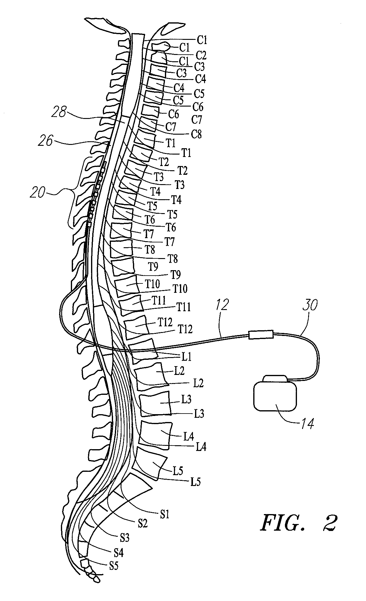
[0023]At the outset, it is noted that the present invention may be used with an implantable pulse generator (IPG) or similar electrical stimulator, which may be used as a component of numerous different types of stimulation systems. The description that follows relates to a spinal cord stimulation (SCS) system. However, it is to be understood that the while the invention lends itself well to applications in SCS, the invention, in its broadest aspects, may not be so limited. Rather, the invention may be used with any type of implantable electrical circuitry used to stimulate tissue. For example, the present invention may be used as part of a pacemaker, a defibrillator, a cochlear stimulator, a retinal stimulator, a stimulator configured to produce coordinated limb movement, a cortical and deep brain stimulator, peripheral nerve stimulator, or in any other neural stimulator configured to treat urinary incontinence, sleep apnea, shoulder sublaxation, etc.

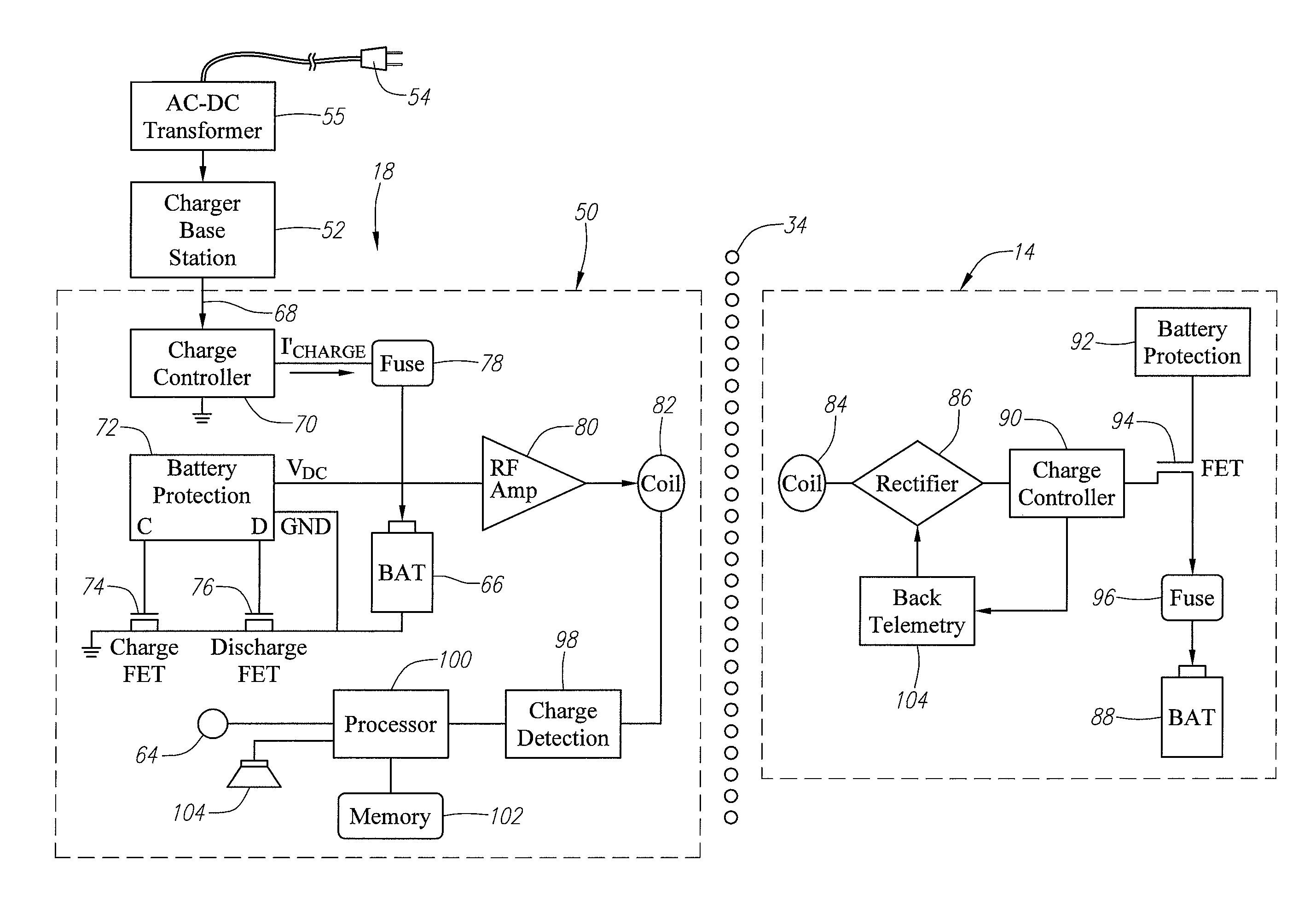
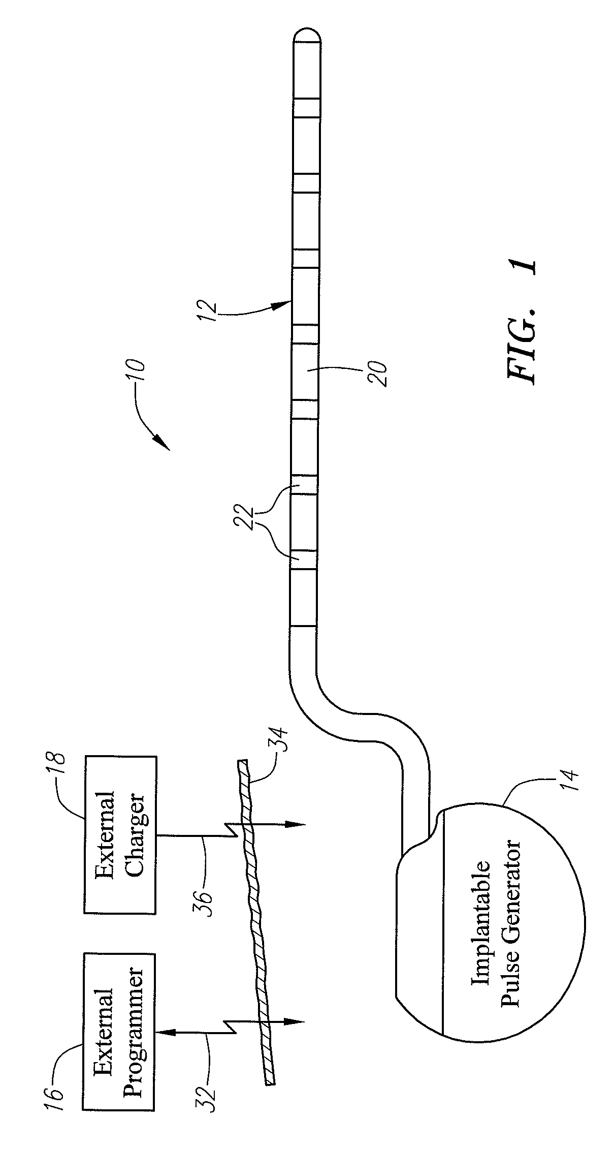
[0024]Turning first to FIG. 1, ...


PUM

PropertyMeasurementUnit
depthsaaaaaaaaaa
DC resistanceaaaaaaaaaa
inductanceaaaaaaaaaa

Abstract

Electrical energy is transmitted to charge the implanted medical device, and an electrical parameter (e.g., a steady-state voltage) indicating a rate at which the implanted medical device is charged by the electrical energy is detected. A threshold (e.g., by modifying a stored threshold value) at which the charge strength indicator generates a user-discernible signal is adjusted based on the detected electrical parameter.

Description

FIELD OF THE INVENTION[0001]The present invention relates to implantable devices, and more particularly, to devices for transcutaneously recharging devices implanted within patients.BACKGROUND OF THE INVENTION[0002]Implantable stimulation devices are devices that generate and deliver electrical stimuli to body nerves and tissues for the therapy of various biological disorders, such as pacemakers to treat cardiac arrhythmia, defibrillators to treat cardiac fibrillation, cochlear stimulators to treat deafness, retinal stimulators to treat blindness, muscle stimulators to produce coordinated limb movement, spinal cord stimulators to treat chronic pain, cortical and deep brain stimulators to treat motor and psychological disorders, and other neural stimulators to treat urinary incontinence, sleep apnea, shoulder sublaxation, etc. The present invention may find applicability in all such applications, although the description that follows will generally focus on the use of the invention w...

Claims


Application Information

Patent Timeline
Patent Type & Authority Patents(United States)
IPC IPC(8): H01M10/46
CPCA61N1/3787
Inventor PETERSON, DAVID K. L.
Owner BOSTON SCI NEUROMODULATION CORP
Why Eureka
Try Eureka