Component stacking using pre-formed adhesive films

a technology of adhesive films and components, applied in the direction of semiconductor devices, semiconductor/solid-state device details, electrical devices, etc., can solve the problems of wlp suffering from drawbacks, adversely affecting the yield, and the packaging of semiconductor dies becoming more difficult, so as to achieve quick pick-and-place and increase the throughput of the bonding process.

Inactive Publication Date: 2011-05-17
TAIWAN SEMICON MFG CO LTD
View PDF7 Cites 4 Cited by
  • Summary
  • Abstract
  • Description
  • Claims
  • Application Information

AI Technical Summary

Benefits of technology

[0012]The advantageous features of the present invention include self-alignment resulting from accurate alignment of the patterned adhesive film with the bottom wafer, and hence quick pick-and-place may be performed. Top dies are automatically aligned to respective bottom dies. The throughput of the bonding process is thus significantly increased.

Problems solved by technology

As a result, the packaging of the semiconductor dies becomes more difficult, which adversely affects the yield.
However, WLP suffers from drawbacks.
With the limited areas of the dies, the number of the I / O pads is limited due to the limitation of the pitch of the I / O pads.
Additionally, under the fixed-ball-size requirement, solder balls must have a certain size, which in turn limits the number of solder balls that can be packed on the surface of a die.
In addition to the above-discussed problems, the conventional die-to-wafer bonding suffers from reliability issues.
Second, if a vacuum is needed in the subsequent process, for example, when a chemical vapor deposition (CVD) step or a physical vapor deposition (PVD) step is involved, bubbles 304 may expand and hence result in damage to devices.

Method used


Image

  • Component stacking using pre-formed adhesive films
  • Component stacking using pre-formed adhesive films
  • Component stacking using pre-formed adhesive films

Examples


Embodiment Construction

[0018]The making and using of the presently preferred embodiments are discussed in detail below. It should be appreciated, however, that the present invention provides many applicable inventive concepts that can be embodied in a wide variety of specific contexts. The specific embodiments discussed are merely illustrative of specific ways to make and use the invention, and do not limit the scope of the invention.

[0019]A novel method of bonding dies onto a wafer is provided. The intermediate stages of performing a preferred embodiment of the present invention are illustrated. Throughout the various views and illustrative embodiments of the present invention, like reference numbers are used to designate like elements.

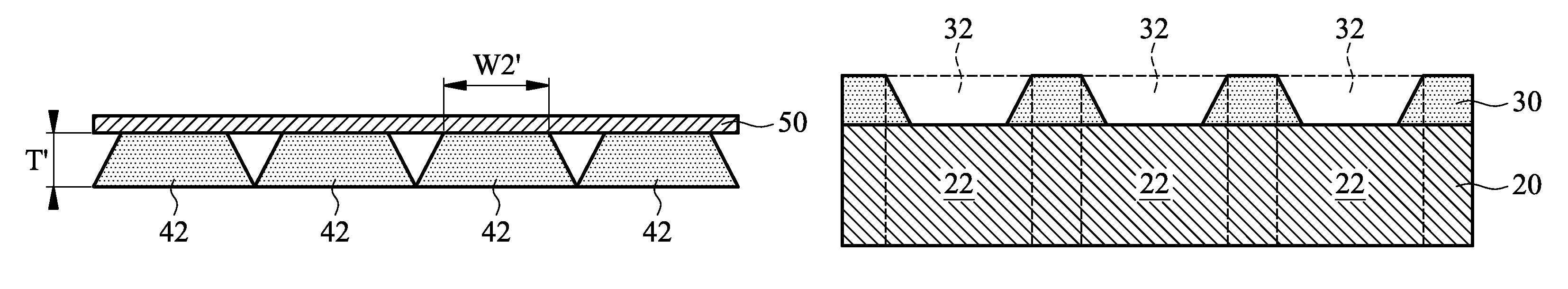
[0020]FIG. 5 is a top view of bottom wafer 20, on which (top) dies will be bonded. Bottom wafer 20 includes a plurality of bottom dies 22, which may be arranged, for example, in the style of an array with a plurality of rows and columns. The positions and sizes of bottom d...


PUM


Abstract

A method of forming integrated circuits includes laminating a patterned film including an opening onto a wafer, wherein a bottom die in the wafer is exposed through the opening. A top die is placed into the opening. The top die fits into the opening with substantially no gap between the patterned film and the top die. The top die is then bonded onto the bottom die, followed by curing the patterned film.

Description

TECHNICAL FIELD[0001]This invention relates generally to integrated circuit manufacturing processes, and more particularly to methods for bonding semiconductor dies onto wafers.BACKGROUND[0002]With the evolution of semiconductor technologies, semiconductor dies are becoming increasingly smaller. However, more functions need to be integrated into the semiconductor dies. Accordingly, the semiconductor dies need to have increasingly greater numbers of I / O pads packed into smaller areas, and the density of the I / O pads rises quickly. As a result, the packaging of the semiconductor dies becomes more difficult, which adversely affects the yield.[0003]Package technologies can be divided into two categories. One category is typically referred to as wafer level package (WLP), wherein dies on a wafer are packaged before they are sawed. WLP technology has some advantages, such as greater throughput and lower cost. Further, less under-fill and / or molding compound is needed. However, WLP suffers...

Claims


Application Information

Patent Timeline
Patent Type & Authority Patents(United States)
IPC IPC(8): H01L23/28
CPCH01L23/3157H01L25/0657H01L25/50H01L2224/16H01L2225/06513H01L2224/0557H01L2224/05573H01L2924/00014H01L2224/05571H01L2224/0554H01L2224/05599H01L2224/0555H01L2224/0556
Inventor WU, WENG-JINTU, HUNG-JUNGYANG, KU-FENGHU, JUNG-CHIHCHIOU, WEN-CHIH
Owner TAIWAN SEMICON MFG CO LTD
Why Eureka
Try Eureka