
Speckle mitigation in laser scanner projector systems

a laser scanner and projector technology, applied in the field of laser scanner projector systems, can solve the problems of high spatial frequency noise in the projected image, noise or severe degradation of image quality, and achieve the effect of reducing speckle in the projected imag

Inactive Publication Date: 2011-05-17
CORNING INC
View PDF25 Cites 11 Cited by
  • Summary
  • Abstract
  • Description
  • Claims
  • Application Information

AI Technical Summary

Benefits of technology

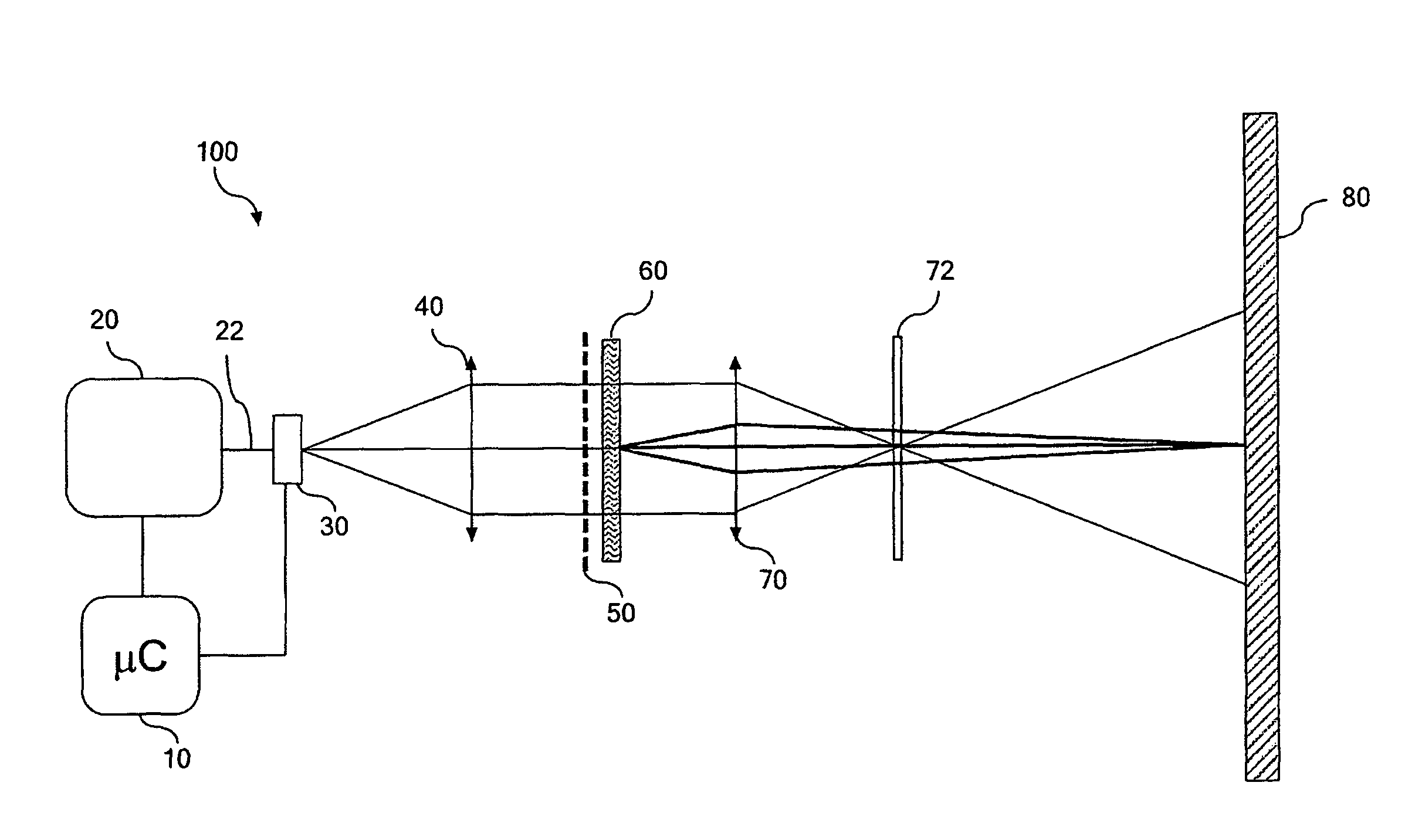
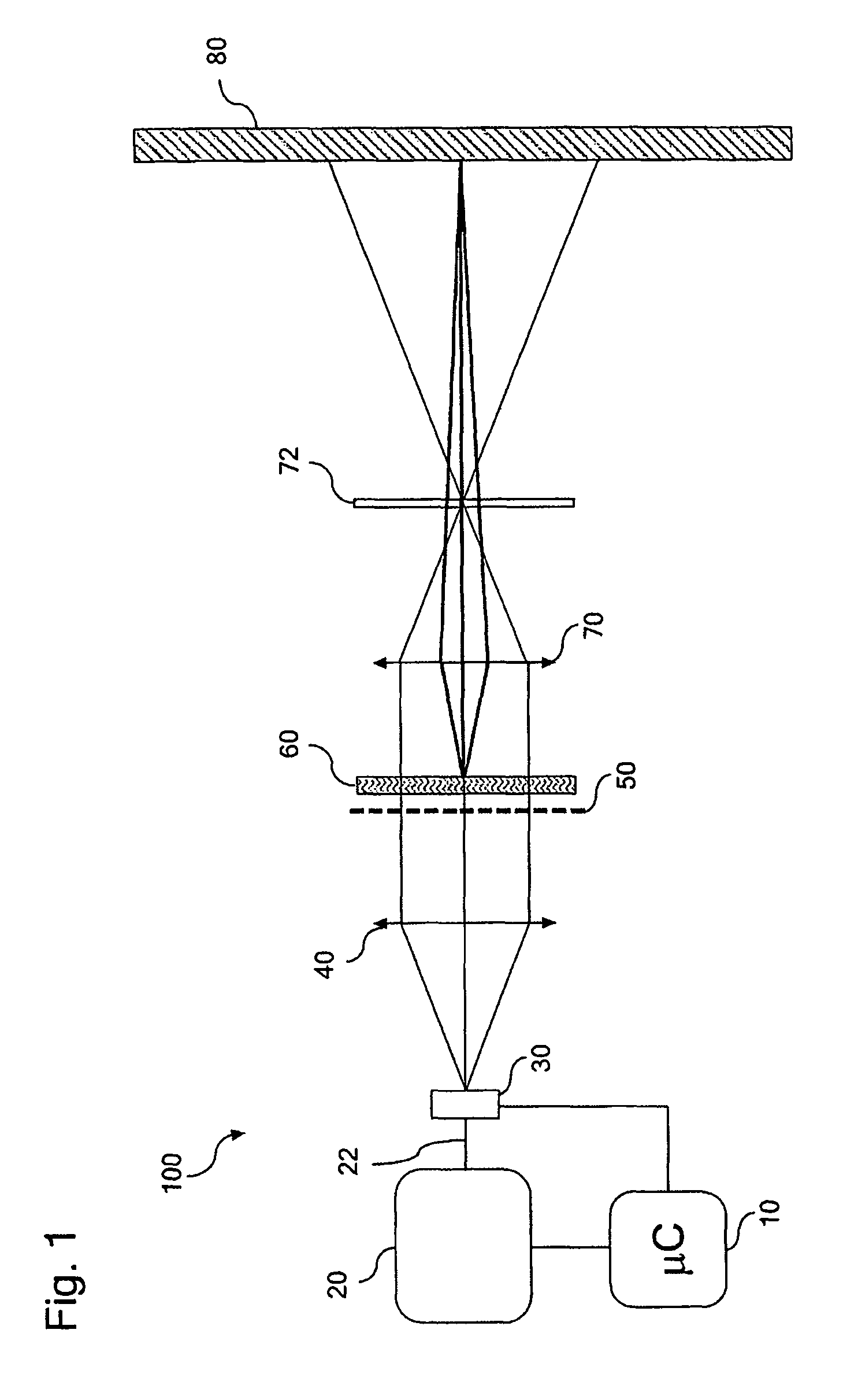
[0011]A method for reducing speckle in the projected image of a laser projection system comprises passing a scanning laser beam comprising encoded image data through a first lens that focuses the laser beam to form an intermediate laser image, passing the scanning laser beam comprising the intermediate laser image through a periodic phase mask having a period that is equal to or greater than a beam waist diameter of the scanning laser beam at the intermediate laser image, generating a plurality of orders of diffraction of the scanning laser beam, projecting the intermediate laser image through a second lens and then through a pupil phase mask to form a projected image on a surface, wherein the projected intermediate laser image comprises a projected scanned output beam that jumps progressively from pixel to pixel to reduce speckle contrast in a the projected image.

Problems solved by technology

Speckle may result whenever a coherent light source is used to illuminate a rough surface, for example, a screen, or any other object that produces a diffused reflection or transmission.
Speckle causes high spatial frequency noise in the projected image.
At an observation point such as an observer's eye or a camera's sensor, these beams can interfere constructively to form a bright spot, or destructively to form a dark spot, producing a random granular intensity pattern known as speckle.
If an image is formed on a screen using laser beams, such granular structure will represent noise or a severe degradation of the image quality.
Although this noise may not be a significant problem when a projector is used to display images, it can be a serious issue when the projector is used to display high spatial frequency content, such as text.
Although rapidly moving the diffuser may provide speckle reduction, it requires an expensive and complicated mechanism to move the phase mask laterally at a relatively high speed.

Method used


Image

  • Speckle mitigation in laser scanner projector systems
  • Speckle mitigation in laser scanner projector systems
  • Speckle mitigation in laser scanner projector systems

Examples


Embodiment Construction

[0016]Particular embodiments may be described in the context of a laser projection system that is configured to scan an output signal or beam across a projection surface to generate a two-dimensional image (e.g., a raster scan). The appearance of speckle in the scanned laser image may be reduced by rapidly creating many different speckle patterns on the projection surface. A human eye or sensor integrates and averages the different speckle patterns and the appearance of speckle is therefore reduced.

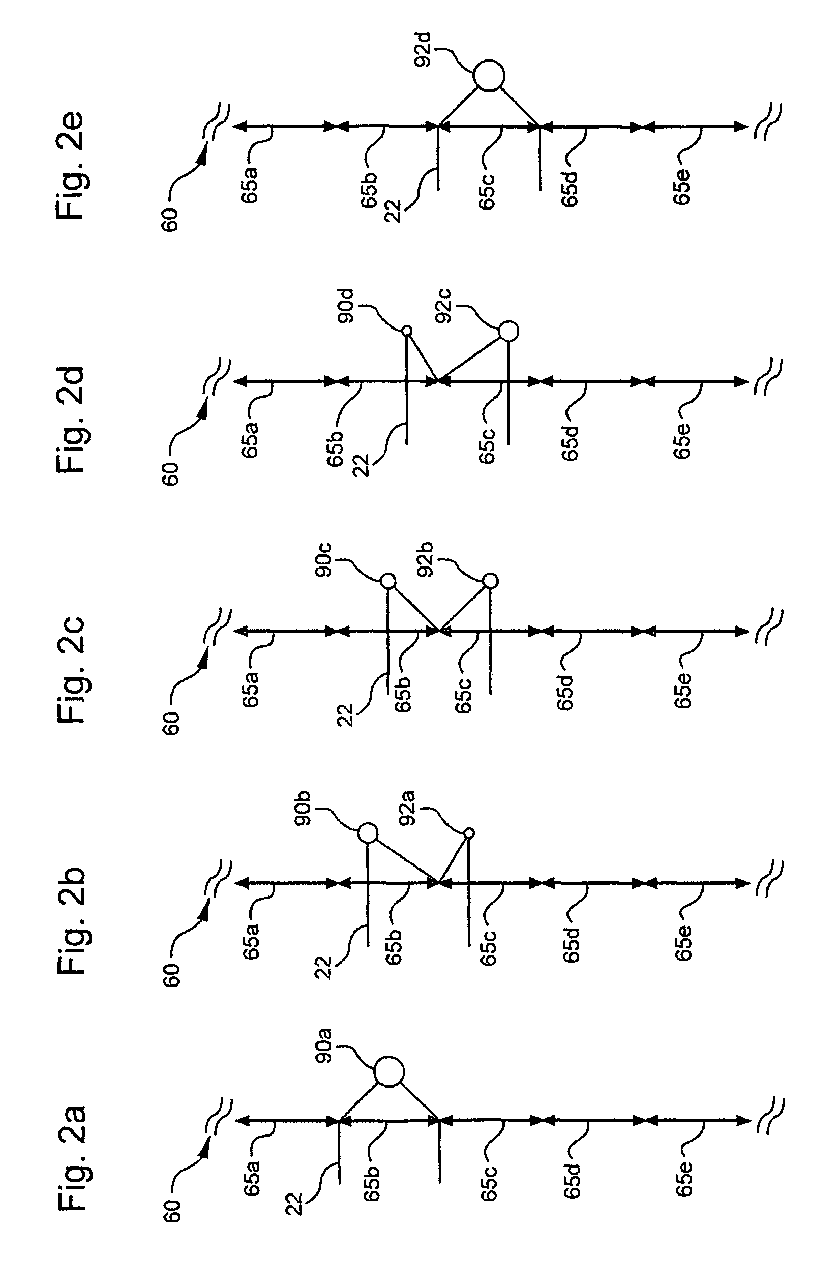
[0017]According to some embodiments, a periodic phase mask is positioned proximate an intermediate laser image formed by projection optics and is configured to reduce the appearance of speckle in a screen or surface by rapidly altering the shape and size of the beam before it is projected onto the screen or surface. The period of the phase mask is approximately equal to or greater than the beam waist diameter of the laser beam used to form the intermediate image at the intermediate image ...


PUM

PropertyMeasurementUnit
waist diameteraaaaaaaaaa
relative phaseaaaaaaaaaa
average angle of incidenceaaaaaaaaaa

Abstract

Laser scanner projection systems that reduce the appearance of speckle in a scanned laser image are provided. The laser projection system includes a visible light source having at least one laser, a scanning element and a system controller. The system controller is programmed to generate a scanned laser image. The system further includes a first lens that focuses a scanned output beam onto an intermediate image and a second lens that projects the intermediate image onto a projection surface. A periodic phase mask having a period that is approximately equal to or greater than the beam waist diameter of the scanned output beam is positioned at the intermediate laser image. The period of the periodic phase mask is such that the projection of the scanned output beam jumps progressively from pixel to pixel, thereby reducing speckle contrast in the scanned laser image.

Description

BACKGROUND[0001]1. Field of the Invention[0002]Embodiments of the present invention relate to laser scanner projection systems. More specifically, embodiments of the present invention relate to laser projection systems and related methods that reduce the appearance of speckle that may be visible in a laser projection image by the use of a periodic phase mask.[0003]2. Technical Background[0004]Speckle may result whenever a coherent light source is used to illuminate a rough surface, for example, a screen, or any other object that produces a diffused reflection or transmission. Particularly, a multitude of small areas of a screen or other reflecting object scatter light into a multitude of reflected beams with different points of origination and different propagation directions. Speckle causes high spatial frequency noise in the projected image. At an observation point such as an observer's eye or a camera's sensor, these beams can interfere constructively to form a bright spot, or de...

Claims


Application Information

Patent Timeline
Patent Type & Authority Patents(United States)
IPC IPC(8): G02F1/01
CPCH04N9/3129G02B27/48
Inventor GOLLIER, JACQUES
Owner CORNING INC
Learn More