
Image processor correcting color misregistration, image processing program, image processing method, and electronic camera

a color misregistration and image processing technology, applied in the field of image processing technology, can solve problems such as color misregistration on captured images, and achieve the effect of high quality

Active Publication Date: 2011-05-17
NIKON CORP
View PDF16 Cites 6 Cited by
  • Summary
  • Abstract
  • Description
  • Claims
  • Application Information

AI Technical Summary

Benefits of technology

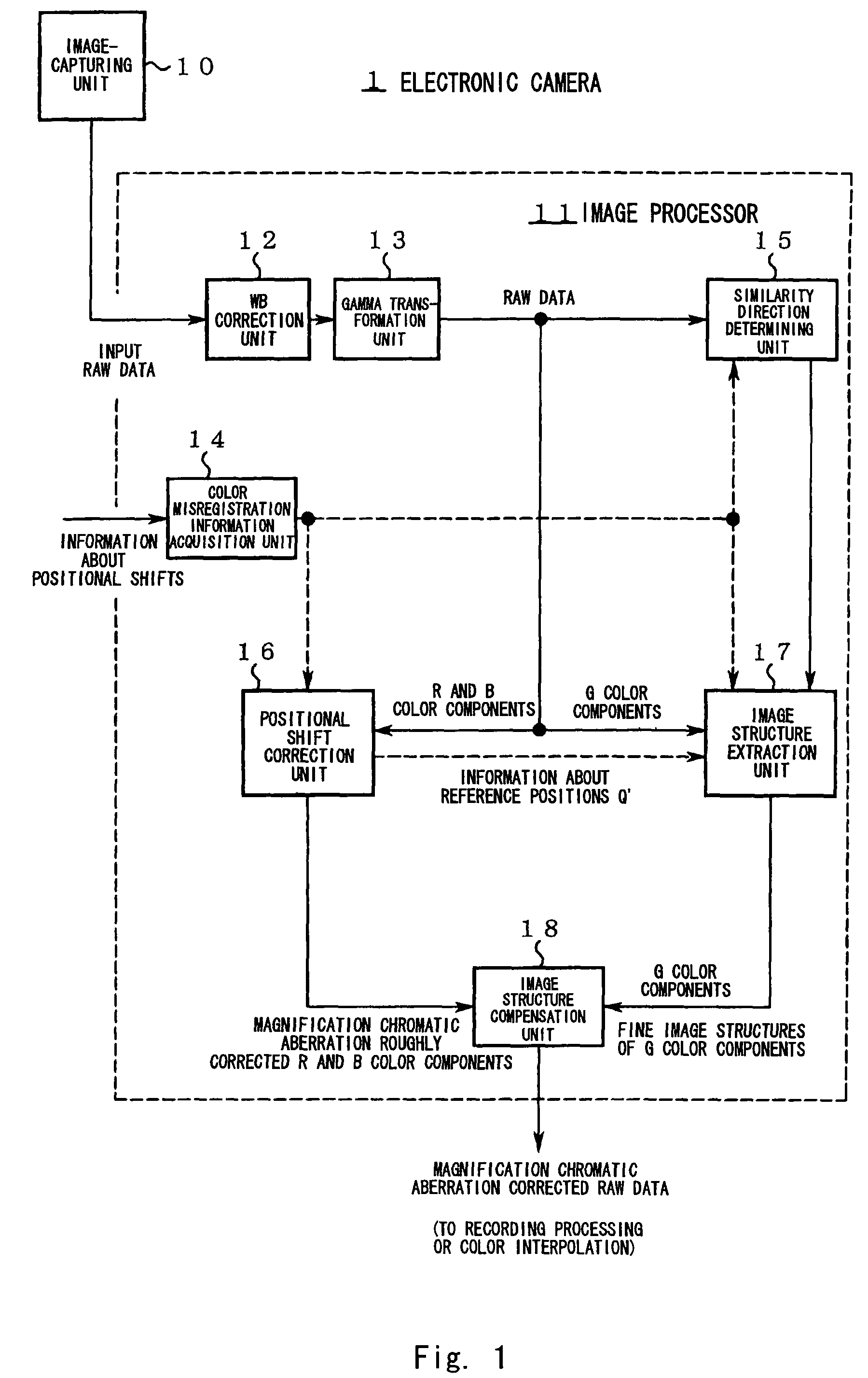
The patent text describes the problem of correcting magnification chromatic aberration for raw data, especially for color components with low pixel densities. The conventional methods mentioned in the text have limitations in preserving fine structures and accurately correcting chromatic color structures. The objective of the present invention is to correct magnification chromatic aberration for raw data with high quality, preserving fine structures and chromatic color structures.

Problems solved by technology

In general, it is known that in an electronic camera, color misregistration occurs on a captured image due to magnification chromatic aberration of an imaging optical system.

Method used


Image

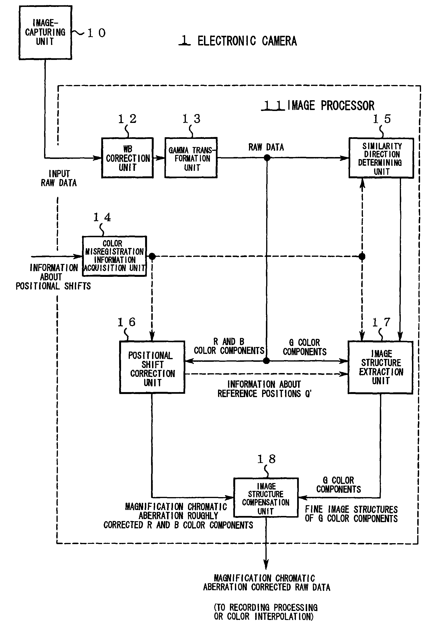
  • Image processor correcting color misregistration, image processing program, image processing method, and electronic camera
  • Image processor correcting color misregistration, image processing program, image processing method, and electronic camera
  • Image processor correcting color misregistration, image processing program, image processing method, and electronic camera

Examples


first embodiment

Operation of First Embodiment

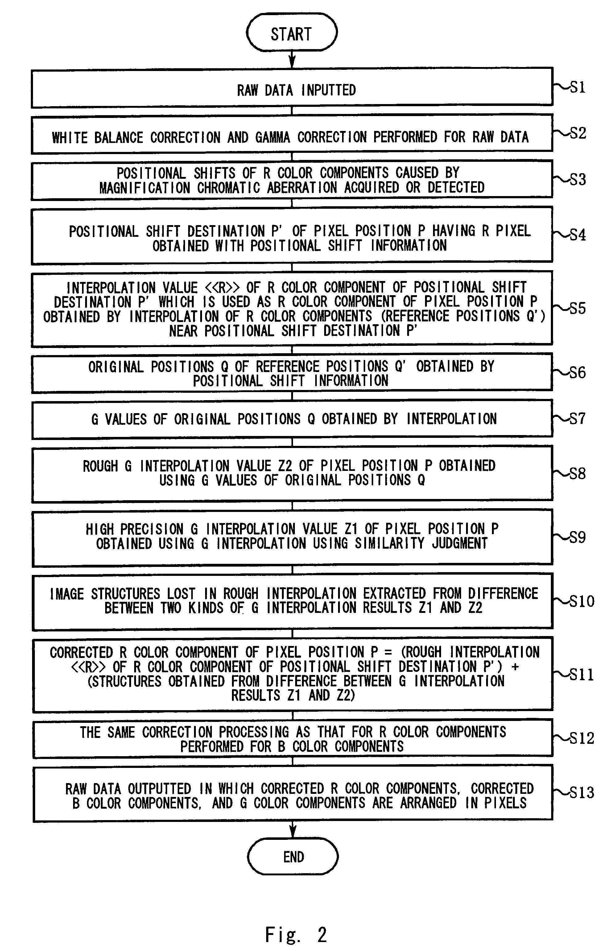
[0084]FIG. 2 is a flow chart showing the processing procedure of the image processor 11. The concrete operation of the first embodiment will be described below along the step numbers in FIG. 2.

[0085]Step S1: Raw data is input to the WB correction unit 12.

[0086]Step S2: The WB correction unit changes signal gains with respect to the R and B color components in the raw data, respectively, to adjust white balance. Usually, the white balance is adjusted in the direction of making the signal levels of the R, G, and B color components even. By this adjustment, signal levels extracted from the G color components at step S10 and signal levels lost from the R and B color components by the positional shift correction performed at step S5 can be made approximately even. Next, the gamma transformation unit 13 performs gamma correction for raw data obtained after the white balance adjustment.

[0087]Step S3: The color misregistration information acquisition unit 14 acq...

second embodiment

Operation of Second Embodiment

[0111]FIGS. 8 and 9 show a flow chart depicting the operation of the image processor 51.

[0112]The concrete operation of the second embodiment will be described below along the step numbers in FIGS. 8 and 9.

[0113]Steps S31 to S33: The same processing as steps S1 to S3 of the first embodiment is performed.

[0114]Step S34: The G interpolation unit 31 obtains original positions P″ before positional shifts with respect to pixel positions P having R color components of raw data (see FIG. 10).

[0115]Step S35: The G interpolation unit 31 performs interpolation with respect to G color components of the raw data to obtain interpolated G color components in the original positions P″. For interpolation performed at this step, a high precision interpolation using similarity judgment is preferable.

[0116]Step S36: The color difference production unit 32 obtains color difference components C″ from the R color components in the pixel positions P and the interpolated G col...


PUM


Abstract

An image processor captures image data which include at least correction object color components and reference color components and has one kind of color component per pixel. The image processor acquires or detects information about positional shifts of the correction object color components and corrects positional shifts of correction object color components. In this correction, image structures lost from correction object color components are compensated for by image structures extracted from reference color components.

Description

CROSS REFERENCE TO RELATED APPLICATION[0001]This application is a U.S. National Stage application claiming the benefit of the prior filed International Application Number PCT / JP2006 / 304079, filed Mar. 3, 2006, in which the International Application claims a priority date of Mar. 4, 2005 based on prior filed Japanese Application Number 2005-061015 the entire contents of which are incorporated herein by reference.TECHNICAL FIELD[0002]The present invention relates to an image processing technology for suppressing magnification chromatic aberration of an image.BACKGROUND ART[0003]In general, it is known that in an electronic camera, color misregistration occurs on a captured image due to magnification chromatic aberration of an imaging optical system. Some technologies for correcting such color misregistration by image processing have been proposed up to now.[0004]For example, in Patent Document 1, when lost color components of raw data are produced by color interpolation, magnification...

Claims


Application Information

Patent Timeline
Patent Type & Authority Patents(United States)
IPC IPC(8): G06K9/00H04N23/12
CPCH04N9/045H04N23/843H04N25/134H04N25/611
Inventor UTSUGI, AKIHIKOISHIGA, KENICHI
Owner NIKON CORP
Learn More