
Frozen block grinder

a grinder and frozen material technology, applied in the field of grinders, can solve the problems of undesired side load on the feed screw, limited number of shearing surfaces that are available, and unfavorable shearing of frozen materials, so as to improve the support of torsional loads, improve the control of blocks, and improve the shearing efficiency

Active Publication Date: 2011-05-24
PROVISUR TECHNOLOGIES INC
View PDF11 Cites 6 Cited by
  • Summary
  • Abstract
  • Description
  • Claims
  • Application Information

AI Technical Summary

Benefits of technology

"The present invention provides a grinding machine with improved shearing efficiency, control of the blocks, and support for the torsional loads placed on the shearing knife. The internal chamber of the grinding machine includes one or more shearing edges that provide fulcrum points against which frozen blocks of material can be held to assist with shearing of the frozen blocks by a feed screw. The feed screw includes fins designed to provide support for the knife as it shears frozen material against the orifice plate. The grinding machine also includes a transition or expansion zone into which frozen material may be fed by the feed screw before ultimately being discharged by further advancement of the feed screw."

Problems solved by technology

This can place an undesirable side load on the feed screw.
Moreover, the spacing of the wall from the feed screw can result in chunks that are sheared from the frozen material undesirably bouncing around as the feed screw rotates.
Another drawback of a conventional grinding machine is the limited number of shearing surfaces that are available.
However, as the block is reduced and / or the chunks of the block are bouncing around, it is difficult to hold the reduced blocks between the feed screw and the internal chamber wall.
Another drawback of conventional hoppers is the lack of post-reduction but pre-discharge volume.

Method used


Image

  • Frozen block grinder
  • Frozen block grinder
  • Frozen block grinder

Examples


Embodiment Construction

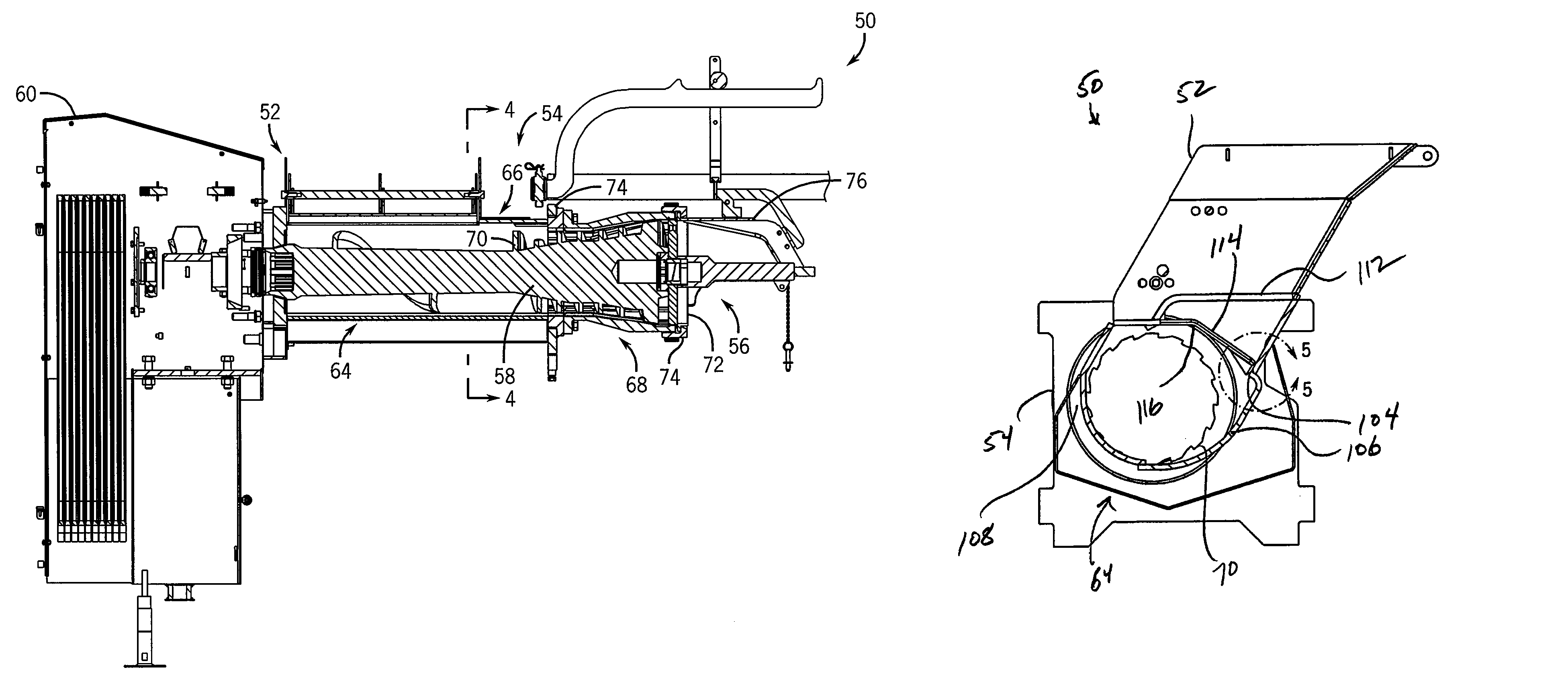
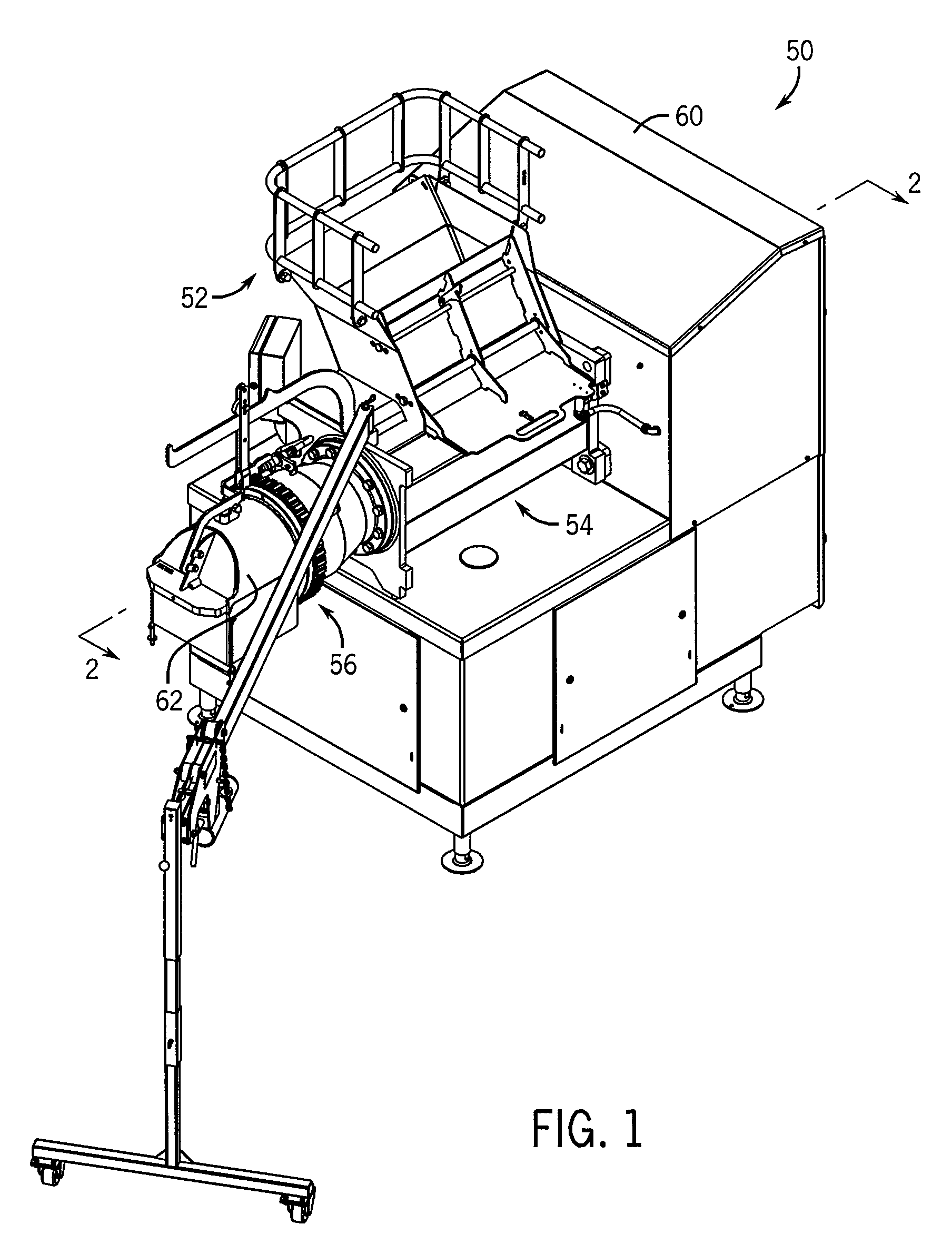
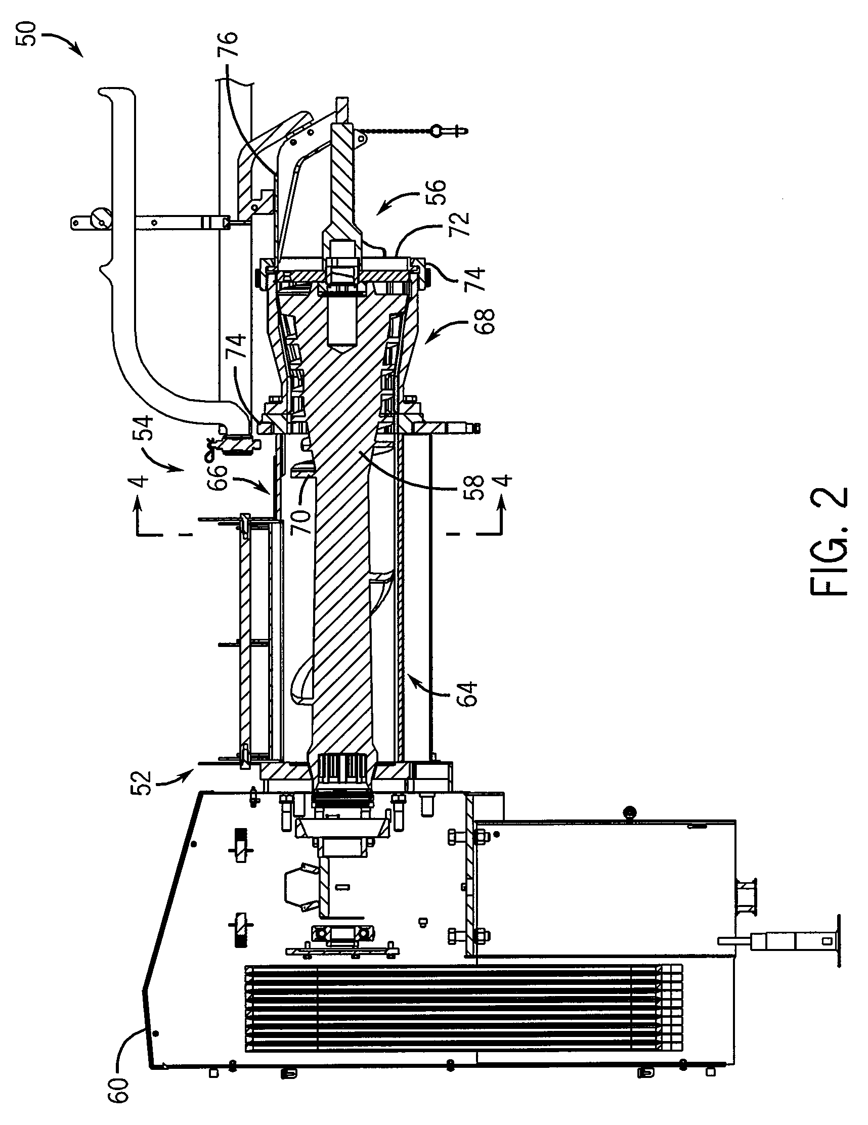
[0028]Referring to FIG. 1, grinding machine 50 has a hopper section 52 and a grinder section 54 which are designed to receive and reduce material, which may be frozen blocks of an edible material such as frozen beef, pork, poultry, or fish. The frozen blocks are reduced by a feed screw assembly 56, which includes a feed screw 58, shown in FIG. 2, and which extends through the grinder section 54. The feed screw assembly 56 includes a drive motor contained within a motor housing 60 that is designed to rotate the feed screw 58. The grinding machine 50 also includes a bulkhead 62 into which the reduced material is fed and collected, as known in the art. It is understood that the grinding machine 50 illustrated is representative and that the present invention may be used with other types of grinding machines.

[0029]Referring now to FIG. 2, grinder section 54 includes a main housing section 64 and a feed section 66. A grinding head section 68 extends forwardly from feed section 66. Feed sc...


PUM


Abstract

A grinding machine has a shearing chamber that includes one or more edges that provide fulcrum points against which frozen block of material, such as frozen blocks of meat, can be held against during a reduction or shearing process. The edges may be arranged to limit the advancement of reduced blocks of material to provide more control on the size of the ground material that is ultimately output by the grinding machine. The grinding machine may also include an expansion zone into which reduced blocks can be temporarily held to accommodate volume increases during the reduction process. A feed screw advances the frozen blocks through the shearing chamber and includes pressure flighting to help shear material from the frozen blocks. The feed screw may include a knife holder that provides support for a knife held therein against the lateral forces experienced by the knife as the knife shears material adjacent the orifice plate.

Description

CROSS-REFERENCE TO RELATED APPLICATION[0001]The present application claims the benefit of U.S. Ser. No. 60 / 946,301, filed Jun. 26, 2007, the disclosure of which is incorporated herein.BACKGROUND AND SUMMARY OF THE INVENTION[0002]The general structure of grinding machines is well known. Typically, a grinding machine has a hopper into which the material to be ground is placed, a grinder portion, including a grinding head, a mounting ring, a bridge, and a collection tube. A feed screw is located within the grinding head to advance material in the hopper through the head. A knife assembly is mounted at the end of, and rotates with, the feed screw and, in combination with the orifice plate, serves to grind material that is advanced toward the orifice plate by the feed screw. Typically, the orifice plate includes collection passages that lead to a collection cavity defined by a collection cone, which supplies material to a discharge passage. An orifice plate guard is located downstream fr...

Claims


Application Information

Patent Timeline
Patent Type & Authority Patents(United States)
IPC IPC(8): B02C18/30B02C19/22
CPCB02C18/301B02C18/2258B02C18/302
Inventor LESAR, NICK J.ALBRECHT, CHRISTOPHER E.WIGHT, E. WILLIAM
Owner PROVISUR TECHNOLOGIES INC
Learn More