
Gardening shears with improved shearing efficiency

a technology of shearing efficiency and shearing shearing, which is applied in the field of garden tools, can solve the problems of long time-consuming and labor-intensive operation mode, and achieve the effects of less effort, simple structure and convenient operation

Active Publication Date: 2016-09-22
LIN THOMAS
View PDF15 Cites 6 Cited by
  • Summary
  • Abstract
  • Description
  • Claims
  • Application Information

AI Technical Summary

Benefits of technology

The present invention is a gardening shears with improved efficiency. It has a simple structure, requires less effort to operate, and has a designed link rod, blade, and control unit to achieve simultaneous shearing actions. The shears have an elongated slot and a guide wheel that allows for easy movement and efficient cutting. The invention also provides a second embodiment with a shorter elongated slot and a toothed arched guide member for additional stability and efficiency. Overall, this invention offers an enhanced gardening experience with reduced effort and improved shearing efficiency.

Problems solved by technology

It is quite laborious to perform this operation mode for a long time.

Method used


Image

  • Gardening shears with improved shearing efficiency
  • Gardening shears with improved shearing efficiency
  • Gardening shears with improved shearing efficiency

Examples


first embodiment

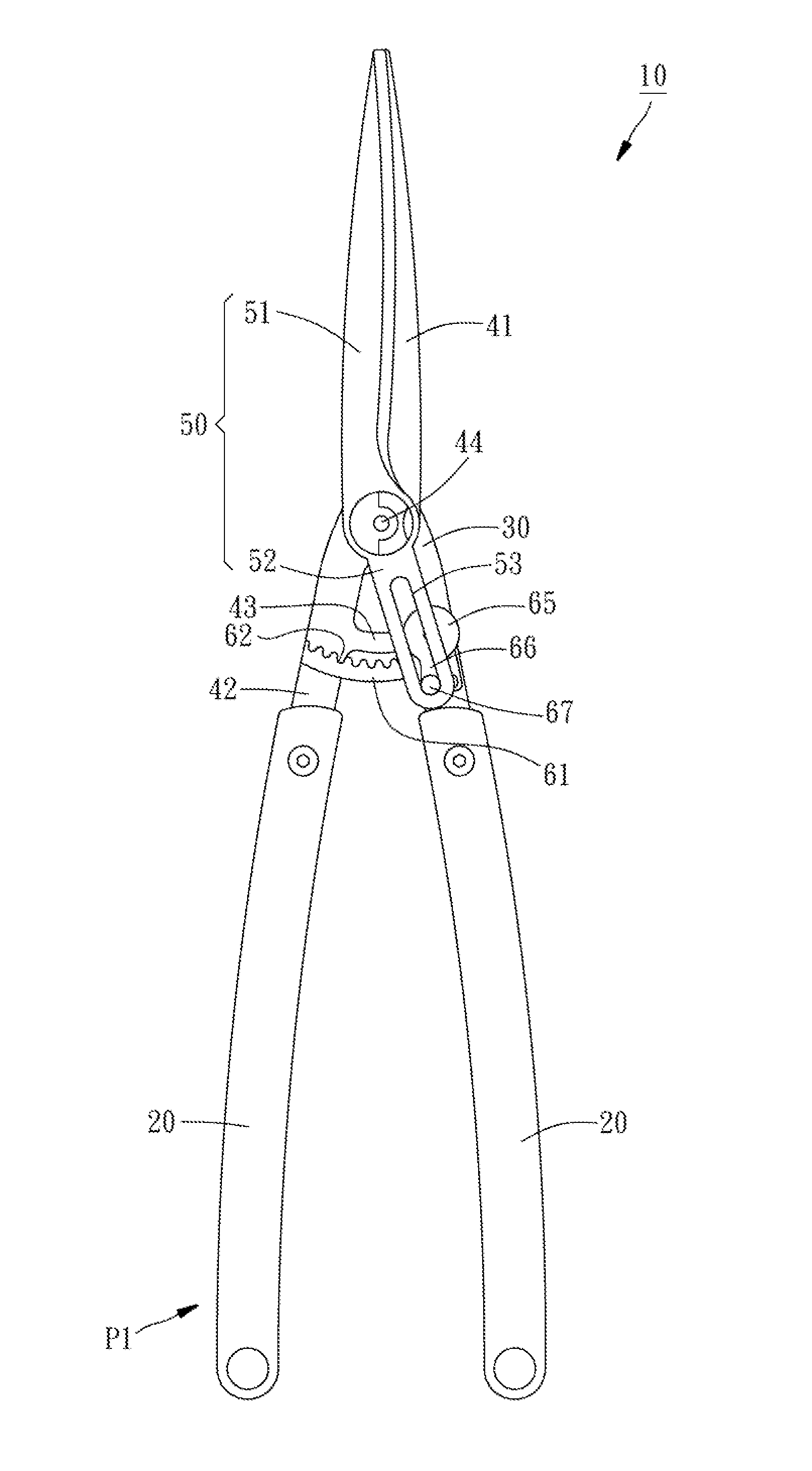
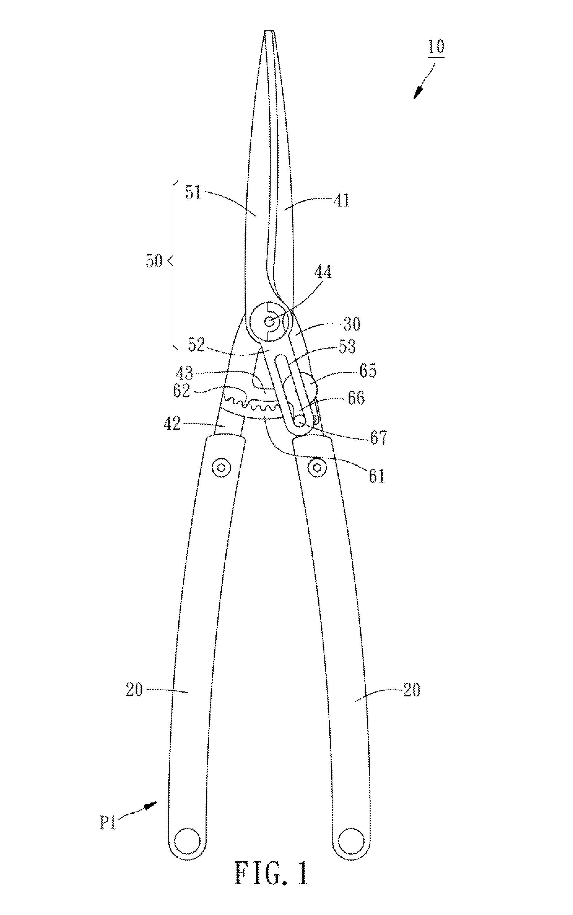
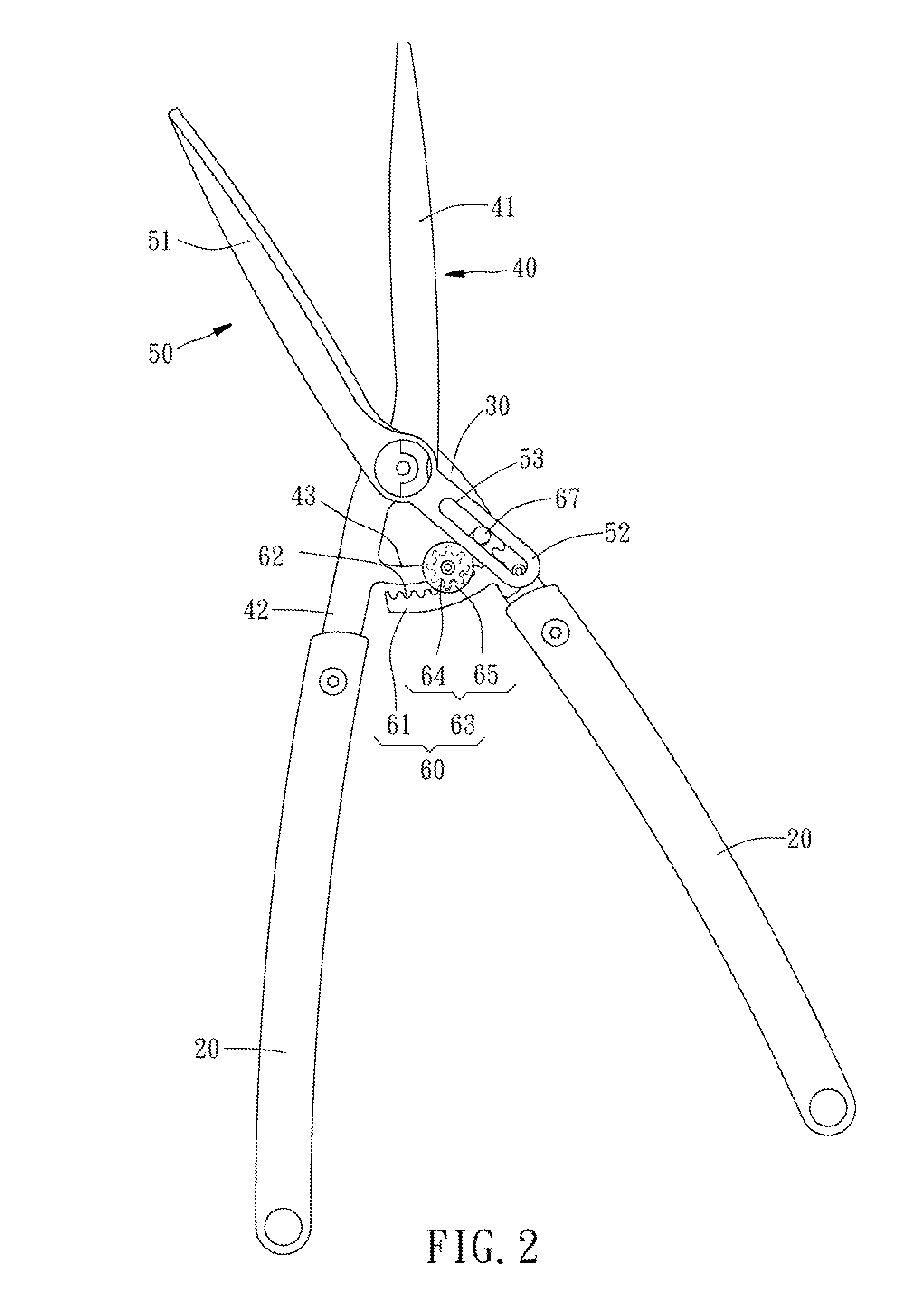
[0016]Referring to FIGS. 1 and 2, a gardening shears 10 in accordance with the present invention is shown. The gardening shears 10 comprises two handles 20, a linking rod 30, a first shear blade 40, a second shear blade 50, and a control unit 60.

[0017]The linking rod 30 has a bottom end thereof fixedly connected to a top end of one handle 20.

[0018]The first shear blade 40 comprises a first cutting blade portion 41, a connection portion 42, and a suspension arm portion 43. The first cutting blade portion 41 has a bottom end thereof pivotally connected to an opposing top end of the linking rod 30 with a pivot 44. The connection portion 42 is extended from the bottom end of the first cutting blade portion 41 and connected to a top end of the other handle 20. The suspension arm portion 43 is extended from an inner peripheral edge of the connection portion 42 in direction toward the linking rod 30. The second shear blade 50 comprises a second cutting blade portion 51, and a bearing porti...

second embodiment

[0024]Further, the structure of the present invention can be variously embodied. For example, in the present invention as shown in FIGS. 4 and 5, the length of the elongated slot 73 of the second shear blade 70 is shortened and less than one half the length of the bearing portion 72 of the second shear blade 70; in order to mate with the length of the elongated slot 73, the wheel cover 83 eliminates the design of the aforesaid extension portion, and, the guiding protrusion 84 is directly mounted at one side of the wheel cover 83 that faces toward the second shear blade 70. Thus, the travel distance of the movement of the guiding protrusion 84 of the wheel cover 83 during rotational movement of the gearwheel 82 along the arched guide member 80 can be reduced one half, shortening the maximum opening angle between the first cutting blade portion 41 of the first shear blade 40 and the second cutting blade portion 71 of the second shear blade 70 to meet different needs.


PUM


Abstract

A gardening shears includes two handles, a first shear blade connected to one handle and providing a suspension arm portion, a linking rod connected to the other handle, a second shear blade coaxially pivoted to the first shear blade and the linking rod and providing an elongated slot, and a control unit including an arched guide member fixedly connected with its one end to the linking rod and a guide wheel pivotally connected to the suspension arm portion of the first shear blade with a guiding protrusion thereof inserted into the elongated slot of the second shear blade.Thus, when opening and closing the handles, the mating arrangement of the arched guide member, the guide wheel and the elongated slot of the second shear blade enables the first and second shear blade to implement the shearing action twice.

Description

BACKGROUND OF THE INVENTION[0001]1. Field of the Invention[0002]The present invention relates to garden tools and more particularly, to gardening shears that significantly improves the shearing efficiency.[0003]2. Description of the Related Art[0004]Conventional gardening shears generally comprise two shear blades pivotally connected together, and two handles respectively connected to respective bottom ends of the shear blades. Moving the two handles with the two hands in direction toward each other can drive the two shear blades to cut branches.[0005]However, after one shearing action, the user needs to pull the two handles outwards to open the two shear blades for a next shearing action, i.e., the user needs to open the two handles and then close them so as to complete one shearing action. It is quite laborious to perform this operation mode for a long time. The shearing efficiency of conventional garden shears needs to be improved.SUMMARY OF THE INVENTION[0006]The present inventi...

Claims


Application Information

Patent Timeline
Patent Type & Authority Applications(United States)
IPC IPC(8): A01G3/025
CPCA01G3/0251A01G3/025
Inventor LIN, THOMAS
Owner LIN THOMAS
Learn More