Shearing device of automatic wire harness binding equipment

A shearing device and automatic technology, applied in the field of wire harness automatic binding system, can solve the problems of poor shearing effect, short service life, low work efficiency, etc.

Active Publication Date: 2016-05-04
GUILIN UNIV OF ELECTRONIC TECH
View PDF6 Cites 6 Cited by
  • Summary
  • Abstract
  • Description
  • Claims
  • Application Information

AI Technical Summary

Problems solved by technology

[0005] The problems to be solved by the present invention are: the volume of the shearing mechanism is too large, the service life is short, the degree of automation is low, the shearing effect is not good, and the work efficiency is low

Method used


Image

  • Shearing device of automatic wire harness binding equipment
  • Shearing device of automatic wire harness binding equipment
  • Shearing device of automatic wire harness binding equipment

Examples


Embodiment Construction

[0022] The present invention will be described in further detail below in conjunction with the accompanying drawings. The following description is only descriptive, and is only an embodiment of the present invention, not all embodiments. Based on the embodiments of the present invention, all embodiments obtained by users in the field on the premise that users do not make creative efforts belong to the protection scope of the present invention.

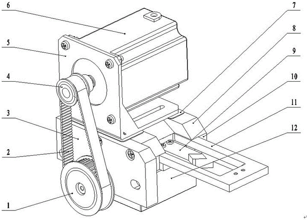
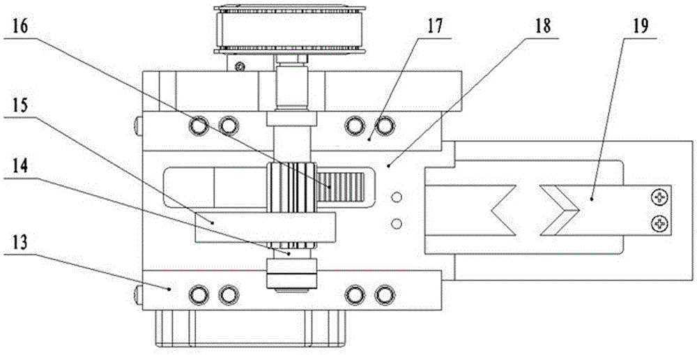
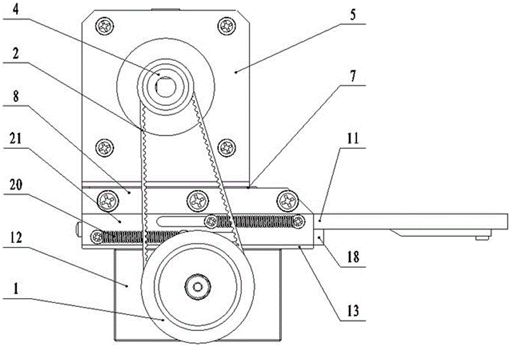
[0023] Such as Figure 1~Figure 5 . A shearing device of automatic wire harness binding equipment includes: a driving mechanism, a transmission mechanism, a shearing mechanism, and a spring return mechanism. The upper part of the whole device is the motor part, and the lower part is the box part 12;

[0024] The driving mechanism includes a motor 6, a small synchronous wheel 4, a large synchronous wheel 1 and a synchronous belt 2 connecting the small synchronous wheel 4 and the large synchronous wheel 1, wherein the motor 6 is fixed ...


PUM


Abstract

The invention discloses a shearing device of automatic wire harness binding equipment. The shearing device comprises a drive mechanism, a transmission mechanism and a shearing mechanism. The upper portion of the whole device serves as a motor part, and the lower portion of the whole device serves as a box part. The drive mechanism comprises a motor, a small synchronizing wheel, a large synchronizing wheel and a synchronizing belt. The transmission mechanism is located in a box and is a gear and rack transmission mechanism, and two racks are fixed to two sliding tool rests of the shearing mechanism. The shearing mechanism comprises the sliding tool rests, blades arranged on the sliding tool rests and sliding rails used for allowing the sliding tool rests to slide. The two sliding tool rests are stacked vertically and can slide oppositely, and the sliding rails are located in the box. The device is short in work time, accurate and stable in shearing action and convenient and easy to operate, a good shearing effect is achieved, the wire harness shearing efficiency is high, and the device can be matched with various kinds of small wire harness binding equipment.

Description

technical field [0001] The invention relates to the field of wire harness automatic binding systems, in particular to a cutting device of wire harness automatic binding equipment. Background technique [0002] With the continuous development of science and technology, the functions of various electronic products continue to increase, there are more and more internal electrical components, and the wiring harness in electronic equipment is becoming more and more dense, especially the development of various large-scale equipment requires a lot of control devices and Components, and the connection of these devices and components needs to pass through complex wire harnesses, which has led to the continuous development of the wire harness industry, and the automatic binding processing equipment for wire harnesses has also emerged as the times require. In the wire harness binding system, the cutting of the wire harness is an important link. [0003] However, in the existing domest...

Claims


Application Information

Patent Timeline
Patent Type & Authority Applications(China)
IPC IPC(8): B21F11/00
CPCB21F11/00
Inventor 李春泉邵永安张明黄红艳赵帅峰王弘扬莫慧光周远畅胡宇威
Owner GUILIN UNIV OF ELECTRONIC TECH
Why Eureka
Try Eureka