System and method for sorting detection of signal egress from a wired communication system

a communication system and signal egress technology, applied in the field of maintenance of wired/cable communication systems, can solve the problems of severe signal egress, slow system operation, and reduce the capacity of the system, and achieve the effect of reducing the number of reports

Active Publication Date: 2011-05-31
COMSONICS
View PDF24 Cites 8 Cited by
  • Summary
  • Abstract
  • Description
  • Claims
  • Application Information

AI Technical Summary

Benefits of technology

[0009]It is therefore an object of the present invention to provide a system and method which minimizes duplication of reports of potential shielding integrity flaws in a wired or cable communication system.

Problems solved by technology

However, a shielding flaw in a wired communication system has substantially symmetrical or complementary effects and thus also permits signal ingress from the environment where electromagnetic signal components at the frequency band(s) of interest are becoming greater over time.
From the standpoint of a cable communication system operator, signal ingress is a severe problem, particularly for digital communications, since corruption of a digital signal packet beyond the degree which can be recovered using error correcting codes (ECCs) and the like requires retransmission of the packet.
The time required for detection of the error and retransmission of packets containing unrecoverable errors slows system operation and reduces capacity of the system.
At the same time, increases in communications, generally, have resulted in continuing increases in electromagnetic signals in the frequency band of interest which complicates signal egress detection.
However, such procedures can result in many reports and work orders which are effectively duplicates and may contain errors due to interference signals being detected as potential signal egress.
Some systems have been developed to validate a detection at a particular frequency as signal egress rather than simply interference signals, but merely sorting even validated reports by location where a validated egress signal is detected, while sufficient for system maintenance, is insufficient to avoid a large number of duplicate work orders since the signal radiation pattern from a shielding integrity flaw without prior information in regard to the nature (e.g. geometry) of the flaw is not readily predictable and a single flaw may be detectable from numerous locations; leading to unnecessary costs and reduced efficiency of operation of the cable communication system.

Method used


Image

  • System and method for sorting detection of signal egress from a wired communication system
  • System and method for sorting detection of signal egress from a wired communication system
  • System and method for sorting detection of signal egress from a wired communication system

Examples


Embodiment Construction

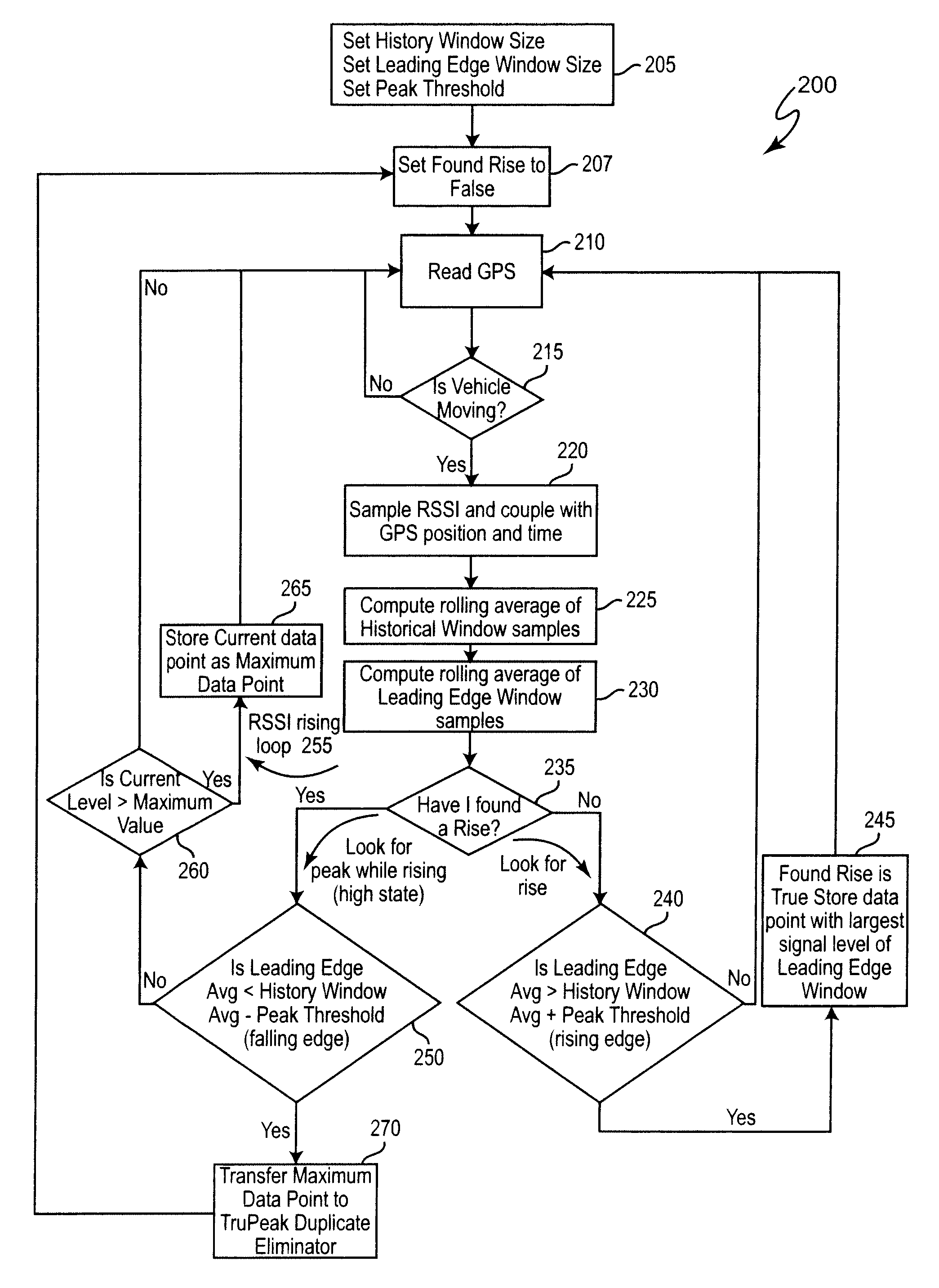
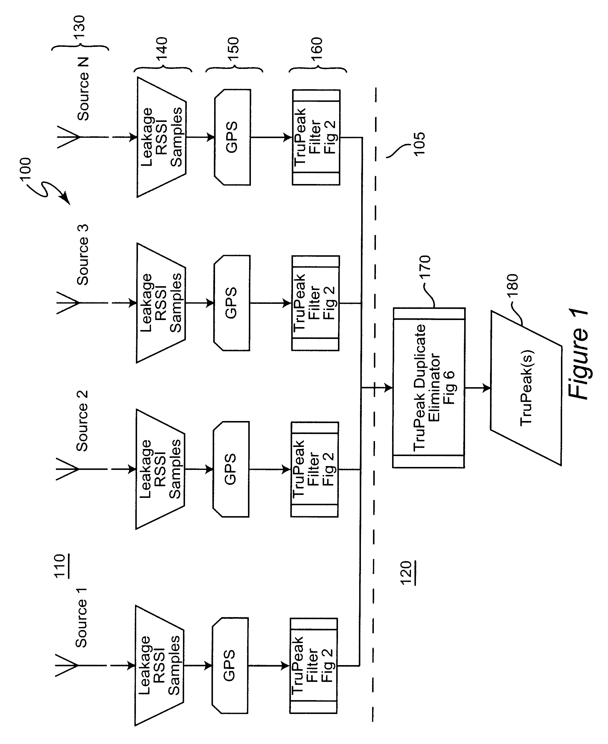
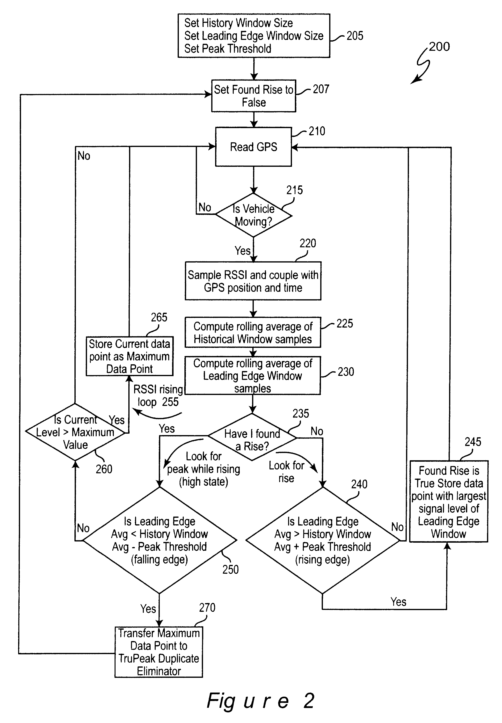
[0019]Referring now to the drawings, and more particularly to FIG. 1, there is shown, in the form of a high-level block diagram, an overview of the system 100 in accordance with the present invention. It will be initially noted that system 100 is divided, as indicated by dashed line 105 into two portions 110 and 120 which is an articulation of the reporting process as indicated above. It may be helpful to observe that portion 110 includes several identical (at the level of abstraction illustrated in FIG. 1) branches and that each of these branches corresponds to a mobile field location for monitoring egress from the cable system and that portion 120 corresponds to processing performed at, for example, a central facility which may or may not be geographically associated with a central facility of the cable system. The invention is applied to components of each of these portions 110, 120 as indicated by the references to FIGS. 2 and 6, respectively and thus no part of FIG. 1 is admitt...


PUM


Abstract

Issuance of work orders in response to monitoring signal egress from shielding integrity flaws in a cable communication system by detecting received signal strength from a mobile receiver only during rising trends in received signal strength when the mobile receiver is in motion and tracking the maximum received signal strength peak during each rising trend. Rising trends are detected by computing two rolling averages of received signal strength sample of different lengths and offset from each other and applying a threshold to the difference between the rolling averages to provide hysteresis in switching between rising and falling trend detection. Reported peaks are then compared by proximity to each other and their circle of influence determined in accordance with respective signal strengths to determine if newly reported peaks are duplicates of previously reported peaks and duplicate reported peaks are removed or discarded.

Description

BACKGROUND OF THE INVENTION[0001]1. Field of the Invention[0002]The present invention generally relates to maintenance of wired / cable communication systems and, more particularly, to detecting and reporting locations of flaws in shielding integrity in the communication system based on signal egress and reporting and remediation thereof.[0003]2. Description of the Prior Art[0004]Wired communication systems have been known for many years and, due to the initial simplicity and limited usage and bandwidth of early systems, the wiring structure was not generally critical to the performance thereof and did not tend to affect operation of other devices proximate thereto or wireless communication systems. At the present time, however, wired communication systems (often referred to as cable telecommunications systems or, simply as cable communications systems or cable systems) use high frequency carrier signals to provide increased bandwidth and information transmission capacity as well as t...

Claims


Application Information

Patent Timeline
Patent Type & Authority Patents(United States)
IPC IPC(8): G01R31/02
CPCG01R29/0892
Inventor JONES, RAYMOND GREGORYEARLY, JOSEPH ROY
Owner COMSONICS
Why Eureka
Try Eureka