Broadcast reception module and broadcast device using the same

a technology of receiving module and broadcast device, applied in the direction of resonant circuit details, selective content distribution, television systems, etc., can solve the problem of time-consuming to specify a viewable channel, and achieve the effect of reducing time and more time for demodulating digital broadcast signals

Inactive Publication Date: 2011-05-31
PANASONIC CORP
View PDF21 Cites 8 Cited by
  • Summary
  • Abstract
  • Description
  • Claims
  • Application Information

AI Technical Summary

Benefits of technology

[0010]The broadcast receiving module and the broadcast equipment using the module of the present invention have solved the aforementioned problem and reduced the time required to specify a viewable channel in channel scanning.
[0012]This structure enables the controller to determine whether the first channel is viewable or not based on the comparison result of the comparator without the need for the demodulator to demodulate the signal of the first channel. Thus, it becomes possible to reduce the time required to specify the viewable channel in channel scanning.
[0014]This structure with the broadcast signal detector enables the controller to determine that the first channel is unviewable when the signal of the first channel has a signal-to-noise ratio not less than a predetermined level due to noise although the signal contains no broadcast signal. This ensures the specification of the viewable channel in channel scanning. In other words, only a signal having a signal-to-noise ratio not less than the predetermined level is demodulated to determine the presence or absence of the broadcast signal. Thus, it becomes possible to reduce the time required to specify the viewable channel in channel scanning.
[0019]In general, a digital broadcast signal has a plurality of combinations of broadcast mode and guard interval. Therefore, the modulation of the digital broadcast signal has to be performed a plurality of times. This means that it takes more time to demodulate a digital broadcast signal than an analog broadcast signal. As a result, detecting the signal-to-noise ratio of the digital broadcast signal before demodulation can greatly reduce the time required to specify the viewable channel during channel scanning.

Problems solved by technology

This makes it time-consuming to specify a viewable channel.

Method used


Image

  • Broadcast reception module and broadcast device using the same
  • Broadcast reception module and broadcast device using the same
  • Broadcast reception module and broadcast device using the same

Examples


first exemplary embodiment

[0039]A broadcast receiving module and broadcast equipment using the module of a first embodiment are described as follows with reference to FIGS. 1 and 2.

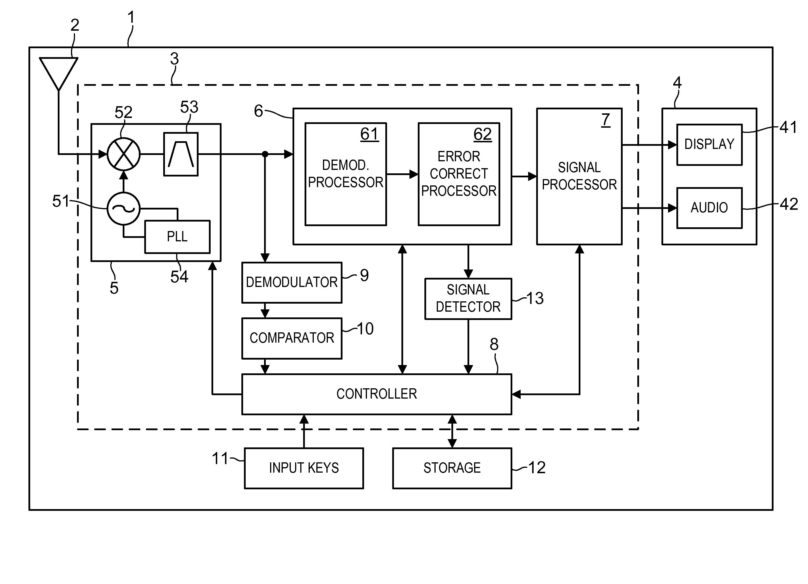
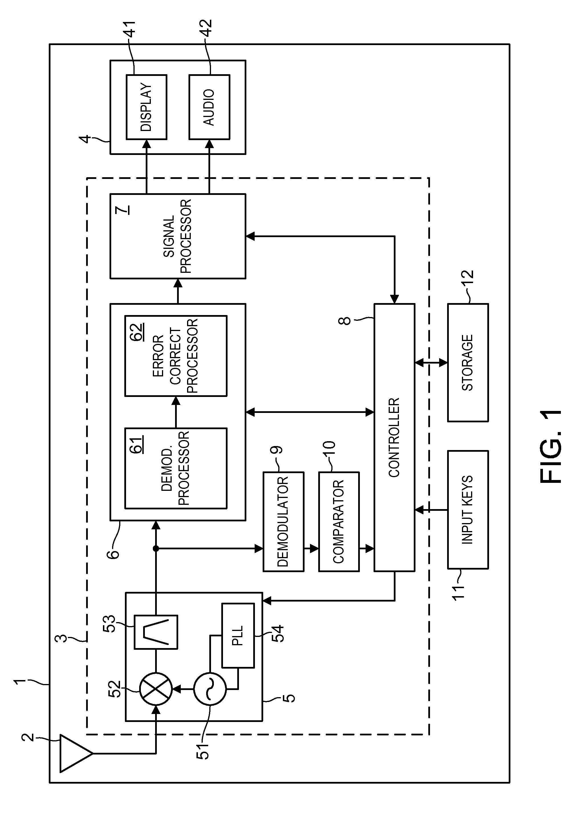
[0040]FIG. 1 is a block diagram of the broadcast equipment of the first embodiment. In FIG. 1, broadcast equipment 1 can be, for example, a portable terminal with TV function or an in-car television. Broadcast equipment 1 includes antenna 2, broadcast receiving module 3, and display unit 4. Broadcast receiving module 3 includes receiver 5, demodulator 6 connected to the output of receiver 5, and signal processor 7 connected to the output of demodulator 6. Receiver 5, demodulator 6, and signal processor 7 are further connected to controller 8. The output of receiver 5 is connected to detector 9 whose output is connected to comparator 10 whose output is connected to controller 8. Controller 8 is further connected to input keys 11 and storage 12. In a case where broadcast equipment 1 is a portable phone or other portable device, a vi...

second exemplary embodiment

[0064]A broadcast receiving module and broadcast equipment using the module of a second embodiment are described as follows with reference to FIGS. 3 and 4. Each component in the present embodiment is identical to its counterpart in the first embodiment unless otherwise noted.

[0065]FIG. 3 is a block diagram of the broadcast receiving module and the broadcast equipment using the module of the second embodiment. In FIG. 3, broadcast receiving module 3 includes broadcast signal detector 13 provided between demodulator 6 and controller 8. Broadcast signal detector 13 determines whether the signal of the first channel demodulated by demodulator 6 contains a broadcast signal or not and informs the determination result to the controller. This broadcast signal can be, for example, TMCC (Transmission and Multiplexing Configuration Control) information as the header of the signal of the first channel.

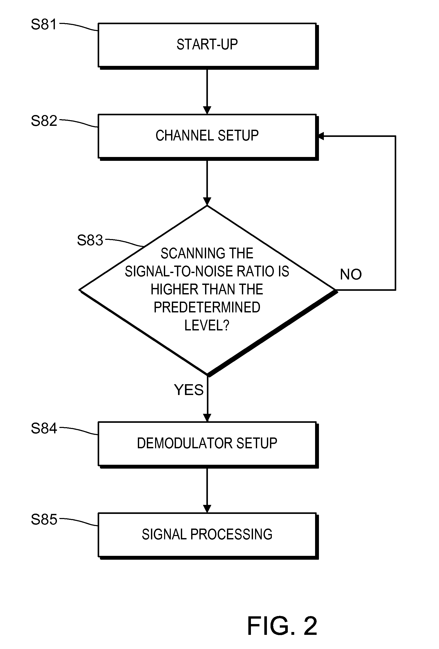
[0066]The operation of the channel scanning by controller 8 of broadcast equipment 1 is descr...

third exemplary embodiment

[0073]A broadcast receiving module and broadcast equipment using the module of the present embodiment are described as follows with reference to FIGS. 5 and 6. Each component in the present embodiment is identical to its counterpart in the first embodiment unless otherwise noted.

[0074]FIG. 5 is a block diagram of broadcast equipment of the third embodiment of the present invention. In FIG. 5, broadcast equipment 1 includes two receivers: first receiver 5a and second receiver 5b. The outputs of first and second receivers 5a and 5b are connected to demodulator 6. The output of second receiver 5b is further connected to detector 9, comparator 10, and controller 8 in that order as in the first embodiment.

[0075]First receiver 5a includes first local oscillator 51a for outputting a signal having a predetermined frequency and first mixer 52a for mixing the signal from first local oscillator 51a with the broadcast signal from first antenna 2a. First receiver 5a further includes first filter...


PUM


Abstract

A broadcast module includes a receiver for selecting the signal of a specific channel from the signals of a plurality of channels under control of a controller; a demodulator connected to the output of the receiver; a detector for detecting the signal-to-noise ratio of the signal selected by the receiver; and a comparator for comparing the signal-to-noise ratio detected by the detector with a predetermined level. The broadcast module can reduce the time required to specify a viewable channel.

Description

[0001]This application is a U.S. National Phase Application of PCT International Application PCT / JP2006 / 313681.TECHNICAL FIELD[0002]The present invention relates to a broadcast receiving module for receiving signals and also to broadcast equipment using the module.BACKGROUND ART[0003]Conventional broadcast equipment 101 is described as follows with reference to drawings.[0004]FIG. 7 is a block diagram of conventional broadcast equipment 101, which includes antenna 102, broadcast receiving module 103, and display unit 104. Broadcast receiving module 103 includes receiver 105, demodulator 106 connected to the output of receiver 105, and signal processor 107 connected to the output of demodulator 106. Receiver 105 selects the signal of a certain channel from the signals of a plurality of channels received by antenna 102. Receiver 105, demodulator 106, and signal processor 107 are further connected to controller 108, which is also connected to input keys 111 and storage 112 including in...

Claims


Application Information

Patent Timeline
Patent Type & Authority Patents(United States)
IPC IPC(8): H04N5/50H03J7/18H04B1/16H04B7/08H04N5/44
CPCH03J1/0066H04N21/4383H04N5/50H03J1/0083H04N21/44209
Inventor YAMAMOTO, SHINJITSUKIO, YASUNOBU
Owner PANASONIC CORP
Why Eureka
Try Eureka