Method and system for creating an illusion of a skylight

a skylight and illusion technology, applied in the field of ceiling lighting systems, can solve the problems of not being practical, failing to trick the eye into believing, and exhibiting unwanted shadows, etc., and achieve the effect of improving realism and being easy and cost-effective to implemen

Active Publication Date: 2011-06-14
THE SKY FACTORY LC
View PDF5 Cites 6 Cited by
  • Summary
  • Abstract
  • Description
  • Claims
  • Application Information

AI Technical Summary

Benefits of technology

[0010]It is an advantage of the present invention to achieve improved realism in the illumination of the panel in that shadows cast by the T-bar are eliminated.
[0011]It is another advantage of the present invention to provide the illusion of a casement-type window frame.
[0012]It is another advantage of the present invention to provide for the ability to easily and cost efficiently implement a trompe l'oeil skylight in a hung ceiling system where the trompe l'oeil skylight appears to be made of a different material than the ceiling grid.
[0013]The present invention is an apparatus and method for providing a trompe l'oeil skylight which is designed to satisfy the aforementioned needs, provide the previously stated objects, include the above-listed features, and achieve the already articulated advantages. The present invention is carried out in a “T-bar shadow-less” manner in a sense that the shadows cast on a translucent image panel by T-bar ceiling grid members, have been eliminated. The invention is also accomplished in “trompe l'oeil” manner in the sense that the appearance of the elevator frame in combination with the lower grid member tricks the eye of the observer into believing it is a casement-type skylight.
[0014]Accordingly, the present invention is a system and method including an elevator frame having a protuberance thereon for restricting horizontal movement of a translucent image panel while it is resting on the elevator frame which is being supported by a T-bar grid system of a hung ceiling.

Problems solved by technology

While this is often very effective at helping to pacify a nervous patient, it is often not practical, especially in interior spaces without roof exposure or in shielded spaces used for radiological imaging or diagnostic equipment which often is required to be in completely enclosed and controlled areas.
While they do tend to create a more pleasant environment, they often fail to trick the eye into believing it is a real skylight, and they often exhibit unwanted shadows created by the T-bar in the hung ceiling grid.

Method used


Image

  • Method and system for creating an illusion of a skylight
  • Method and system for creating an illusion of a skylight
  • Method and system for creating an illusion of a skylight

Examples


Embodiment Construction

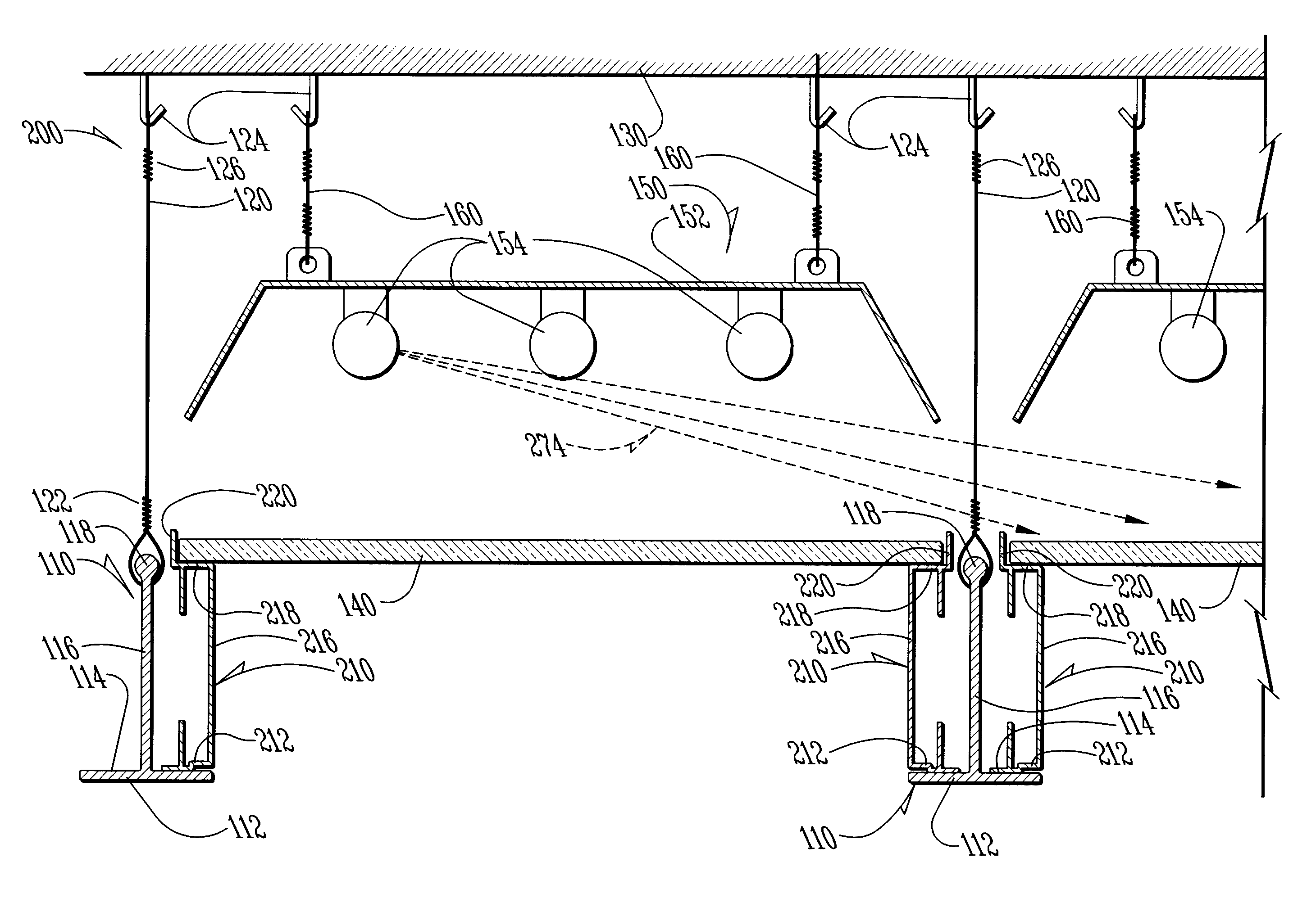
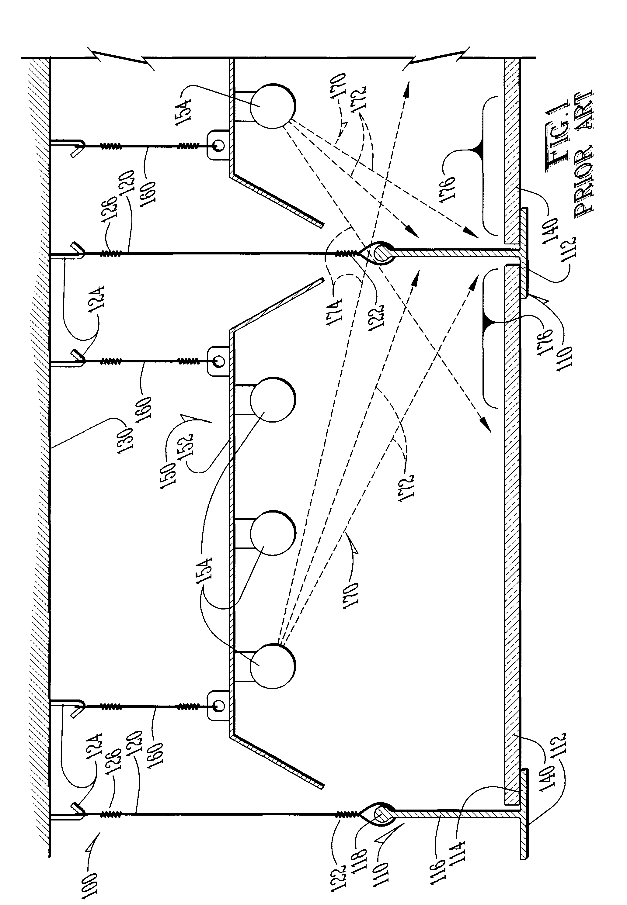
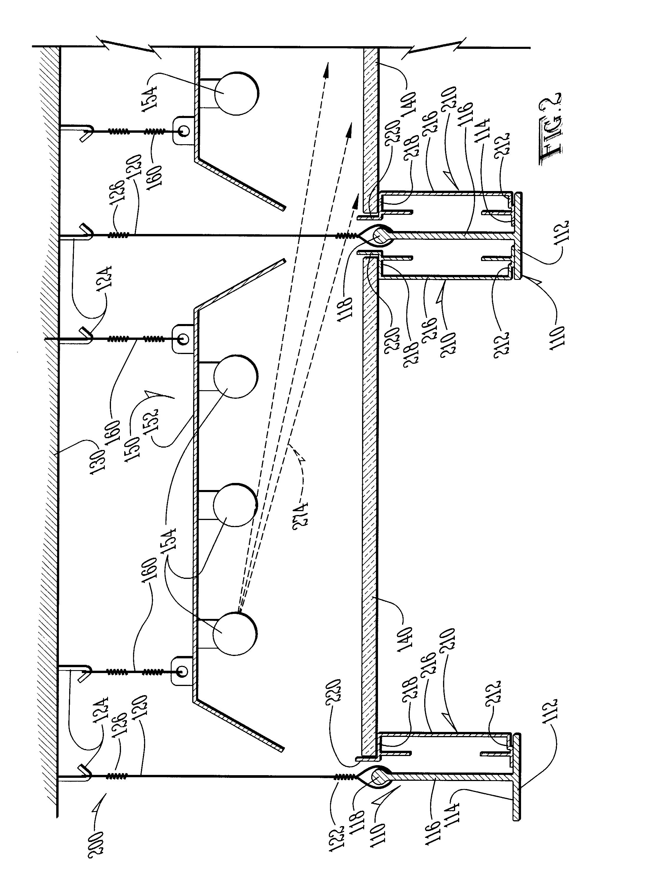
[0021]Now referring to the drawings wherein like numerals refer to like matter throughout, and more specifically referring to FIG. 1, there is shown a side view of a hung ceiling system of the prior art generally designated 100 which includes a translucent sky image panel 140. This end view or cross-sectional view is of a translucent sky image panel disposed with a T-bar grid member 110 on each side. The T-bar grid member 110 is a long linear T-shaped element which has a T-bar grid member bottom surface 112 which is visible to the consumer along with other translucent sky image panels 140 and other ceiling tiles (not shown). T-bar grid member 110 has a T-bar grid member bottom shelf 114 where the translucent sky image panel 140 or a regular ceiling tile would rest. T-bar grid member 110 has a T-bar grid member vertical member 116 and a T-bar grid member top portion 118 which is coupled to a T-bar suspension wire 120 by a T-bar suspension wire bottom winding 122. T-bar suspension wir...


PUM


Abstract

A system and method for creating a trompe l'oeil skylight in a T-bar type hung ceiling system where a translucent panel with an image of a sky scene is elevated above a T-bar grid, by a frame, so as to eliminate shadows of the T-bar on the image panel and so as to simulate a casement-type skylight.

Description

CROSS-REFERENCE TO RELATED APPLICATION[0001]This application is a continuation of application Ser. No. 10 / 908,940 filed on Jun. 1, 2005, by the same inventors, with the same title as the within application.FIELD OF THE INVENTION[0002]The present invention generally relates to ceiling lighting systems, and more particularly relates to ceiling lighting systems with a hung grid for holding ceiling panels, and more particularly relates to methods and systems for creating an illusion of a skylight in such a hung ceiling system.BACKGROUND OF THE INVENTION[0003]In recent years, medical professionals have used various types of methods to calm a patient who is undergoing or waiting for an important medical procedure. One example is the use of a skylight so the patient can have a view of the outdoors. While this is often very effective at helping to pacify a nervous patient, it is often not practical, especially in interior spaces without roof exposure or in shielded spaces used for radiologi...

Claims


Application Information

Patent Timeline
Patent Type & Authority Patents(United States)
IPC IPC(8): F21S8/00
CPCE04B9/32F21S8/04F21V3/00F21V21/049Y10S362/812Y10S362/806F21W2131/205F21Y2113/00
Inventor SCHREIBER, RADIMWITHERSPOON, SKYE
Owner THE SKY FACTORY LC
Why Eureka
Try Eureka