Simulated anatomical structures incorporating an embedded image layer

a technology of anatomical structures and embedded images, applied in the field of simulated physiological structures, can solve the problems of inability to paint elastomeric materials to provide a real life appearance of tissue, uniform appearance to be very lifelike, and inability to achieve the effect of enhancing the realism of the simulated tissue structure, enhancing the tactile response, and increasing the resistance to incision

Active Publication Date: 2010-12-14
TOLY CHRISTOPHER C
View PDF71 Cites 79 Cited by
  • Summary
  • Abstract
  • Description
  • Claims
  • Application Information

AI Technical Summary

Benefits of technology

[0010]A single simulated physiological structure can include a plurality of different image layers. For example, a simulated physiological structure representing a simulated tissue structure (and having dermal and sub-dermal tissue layers) includes a plurality of different layers of elastomeric materials. A plurality of image layers are preferably incorporated into such a simulated physiological structure to enhance the realism of the simulated physiological structure. A first image layer corresponds to skin, and includes variations in shading and color, as exhibited by real human skin. Preferably, the image layer will be printed onto a fabric substrate, using a real image of human skin as the source of the image. Such an image should include features normally associated with human skin, including such features as hair, freckles, variations in color and shading, and occasional imperfections, such as scars, bruises, abrasions, and tattoos. The resulting image layer is coupled to an elastomeric material selected to represent a dermal layer. If desired, a thin layer of relatively clear elastomeric material can be placed over the image layer, so that the upper surface of the simulated tissue structure has the tactile feel of tissue and does not look or feel like fabric. An image layer can also optionally include skin abnormalities such as wounds.
[0012]The specific substrate selected for use in an image layer will be a function of the specific simulated physiological structure, and a disposition of the image layer with respect to the specific simulated physiological structure. In a simulated tissue structure, where such a simulated tissue structure is configured to be incisable, adding fibrous layers (having different thicknesses and textures) at selected positions can enhance the realism of the simulated tissue structure so that the simulated tissue structure responds to incisions much like real tissue. A fibrous layer can be included adjacent to the dermal layer, so that the dermal layer will provide more resistance to incision than a sub-dermal layer, which corresponds to softer tissue. Additional fibrous layers can be added deeper into the simulated tissue structure, to simulate serous membranes. Where an image layer is desired adjacent to a fibrous layer that is included to enhance a tactile response (for example, near the dermal layer), the substrate onto which the image is to be printed can be the fibrous layer selected to enhance the tactile realism of the simulated physiological structure. Also, where an image layer is desired, and no fibrous layer is needed for tactile response (or where inclusion of a fibrous layer would provide an unrealistic tactile response), a substantially non-fibrous substrate can be selected. For example, a plastic substrate can be used in place of a fabric or fibrous substrate. Presentations using overhead projectors often employ images and text that have been printed onto transparent plastic sheets (generally referred to as transparency films). Such transparent sheets can be used as a substrate material where a fibrous substrate is undesirable.
[0013]Selecting an image of tissue exhibiting a diseased or abnormal condition, for incorporating into an image layer enables very realistic training models to be achieved. For example, an image of a wound that penetrates the skin layer can be selected for an image layer. The image layer is then incorporated into a simulated tissue structure to achieve a simulated tissue structure that accurately visual depicts a wound. Because wounds often change the contours of the skin layers at the wound site, the contours of the wound can be reproduced in an elastomeric layer corresponding to a dermal tissue layer as it would appear if affected by an actual wound. The image layer is draped over the contoured elastomeric layer, so that the image of the wound is properly positioned relative to the contours of the elastomeric layer.
[0014]Images of disease conditions associated with organs can also be employed. For example, a simulated stomach might have an elastomeric layer simulating the lining of the stomach. An image of a stomach ulcer can be selected, and an image layer generated using this image. The resulting image layer is coupled to the elastomeric layer to achieve a realistically appearing simulated physiological structure (a model of a stomach including an ulcer). As noted above, if desired, the elastomeric layer simulating the stomach lining can include contours corresponding to those of a true ulcer. When the image layer is properly positioned relative to the elastomeric layer, the model can be used for video endoscopic training exercises. A student examining this model with a real or simulated endoscope can examine the interior of the stomach and discover a visually realistic appearing ulcer.

Problems solved by technology

While elastomeric materials can realistically tactilely simulate soft tissues, from a visual perspective, elastomeric materials are not as lifelike as would be desired.
Dyes and colors can be added to elastomeric materials to achieve a more lifelike appearance, but even such flesh-colored elastomeric materials are too uniform in appearance to be very lifelike.
While rigid plastics can readily be painted, elastomeric materials cannot easily be painted to provide a real life appearance of tissue.

Method used


Image

  • Simulated anatomical structures incorporating an embedded image layer
  • Simulated anatomical structures incorporating an embedded image layer
  • Simulated anatomical structures incorporating an embedded image layer

Examples


Embodiment Construction

Overview of the Present Invention

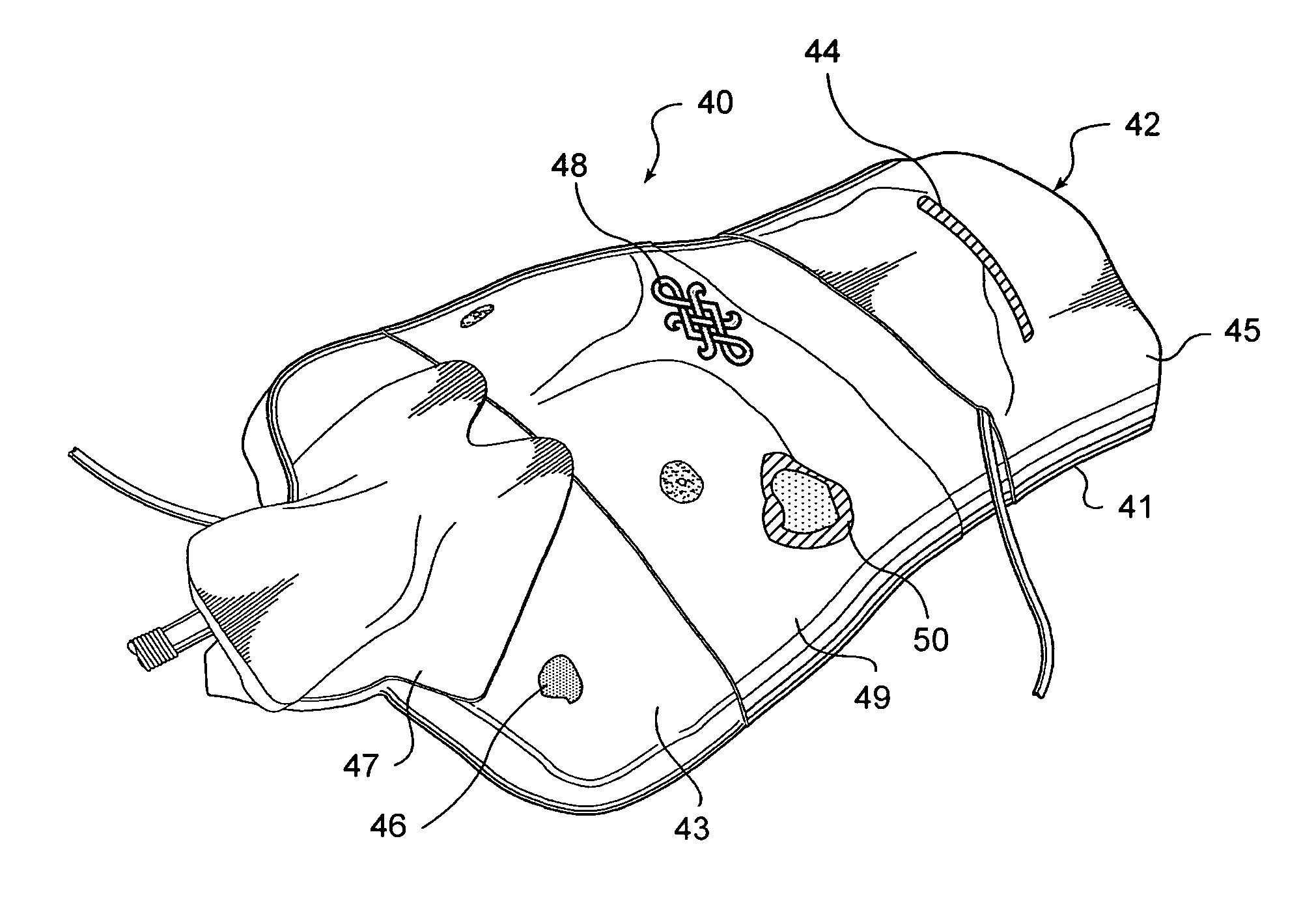
[0027]Medical models have been developed that provide very realistic tactile representations of tissue by incorporating layers of elastomeric materials that simulate dermal layers, muscle, fat, and other soft tissue structures, and organs. Such elastomeric materials can be dissected, much like actual tissue, and provide tactilely realistic sensations to the student. However, elastomeric materials cannot readily be painted to achieve a visually realistic model, the way that hard plastic materials can be, because paint does not adhere well to elastomeric materials, and does not produce a visually realistic effect.

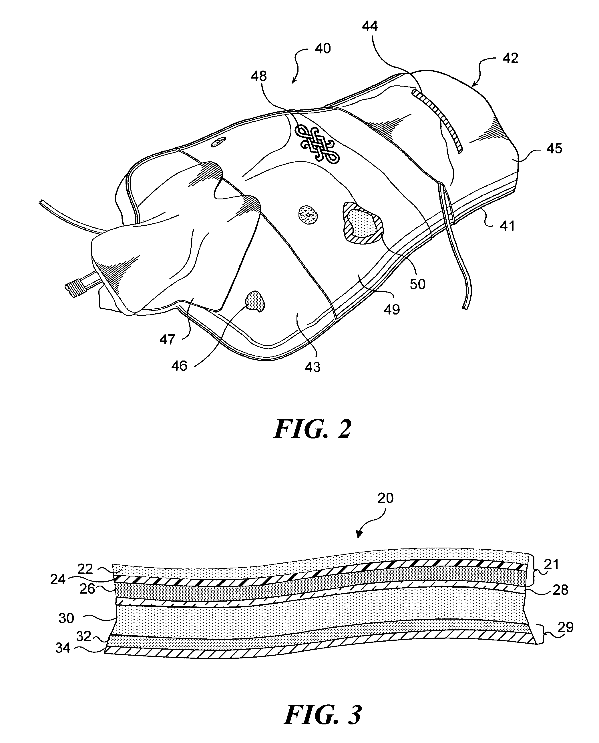
[0028]In the present invention, an image layer is used to enable very visually realistic medical models to be achieved, even when elastomeric materials are used for creating the models. An image of an appropriate physiological structure is printed onto a substrate to generate an image layer. That image layer is then incorporated into a simulat...


PUM


Abstract

A simulated physiological structure includes an image layer configured to enhance a visual appearance of the simulated physiological structure. The image layer includes a substrate onto which an image has been printed. Preferably, the substrate is a relatively thin layer, compared to other layers of material in the simulated physiological structure. Where the simulated physiological structure includes surface irregularities, the substrate is preferably sufficiently thin so as to be able to readily conform to the surface irregularities. Particularly preferred substrates include fabrics, fibrous materials, meshes, and plastic sheets. The image, which can be of an actual anatomical element, or a rendering of an anatomical element, is transferred onto the substrate using conventional printing technologies, including ink jet printing. Particularly preferred images illustrate vascular structures and disease conditions. Preferably, the substrate is coupled to an elastomeric material that forms at least part of the simulated physiological structure.

Description

RELATED APPLICATIONS[0001]This application is a continuation-in-part of a copending patent application, Ser. No. 10 / 718,492, filed on Nov. 20, 2003, which itself is a continuation-in-part of prior application Ser. No. 09 / 695,380, filed on Sep. 23, 2000 (and issued as U.S. Pat. No. 6,780,016), the benefit of the filing dates of which is hereby claimed under 35 U.S.C. §120.FIELD OF THE INVENTION[0002]The present invention generally pertains to simulated physiological structures for use as medical training aids, and more specifically, to simulated physiological structures that include an image layer incorporated into the simulated physiological structure to enhance the realism of the simulated physiological structure.BACKGROUND OF THE INVENTION[0003]The use of simulated physiological structures for training medical students and for providing skill training to practicing physicians is widespread. Although cadavers have traditionally been beneficially employed for this purpose, cadavers ...

Claims


Application Information

Patent Timeline
Patent Type & Authority Patents(United States)
IPC IPC(8): G09B23/28G09B23/30
CPCG09B23/28G09B23/285G09B23/30
Inventor TOLY, CHRISTOPHER C.
Owner TOLY CHRISTOPHER C
Why Eureka
Try Eureka