
Weld characteristic communication system for a welding mask

a communication system and welding mask technology, applied in protective garments, manufacturing tools, eye treatment, etc., can solve the problems of poor overall weldments, inexperienced welding operators often have difficulty establishing the proper torch angle and torch-to-workpiece distan

Active Publication Date: 2011-06-21
ILLINOIS TOOL WORKS INC
View PDF37 Cites 92 Cited by
  • Summary
  • Abstract
  • Description
  • Claims
  • Application Information

AI Technical Summary

Benefits of technology

The present patent is about a system and method for transmitting real-time weld characteristic information to a welding operator in an intuitive way. The system uses visual and audio cues to indicate the direction and severity of torch angle errors and the distance between the torch and the workpiece. The system includes arrays of visual indicators on the welding helmet or goggles, or a belt pack. The technical effect of this patent is to provide a more efficient and effective way of communication for welding operators, allowing them to quickly identify and correct any errors in the welding process.

Problems solved by technology

For instance, an improper torch angle can lead to spatter, improper penetration, and overall poor weldments.
However, inexperienced welding operators often have difficulty establishing the proper torch angle and torch-to-workpiece distance during welding, and such parameters may be somewhat difficult to estimate during the process of making a weld.
Furthermore, even experienced welding operators may have difficulty monitoring and maintaining these important parameters throughout welding processes.
It is now recognized that such traditional methods may lead to excess consumable waste, especially during training exercises.

Method used


Image

  • Weld characteristic communication system for a welding mask
  • Weld characteristic communication system for a welding mask
  • Weld characteristic communication system for a welding mask

Examples


Embodiment Construction

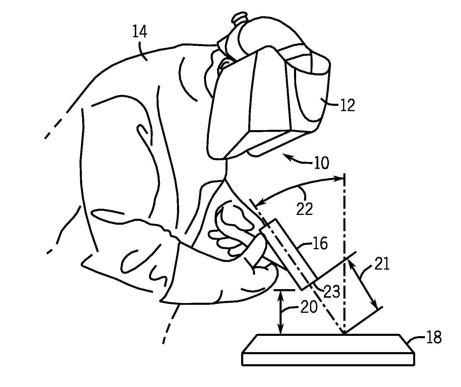
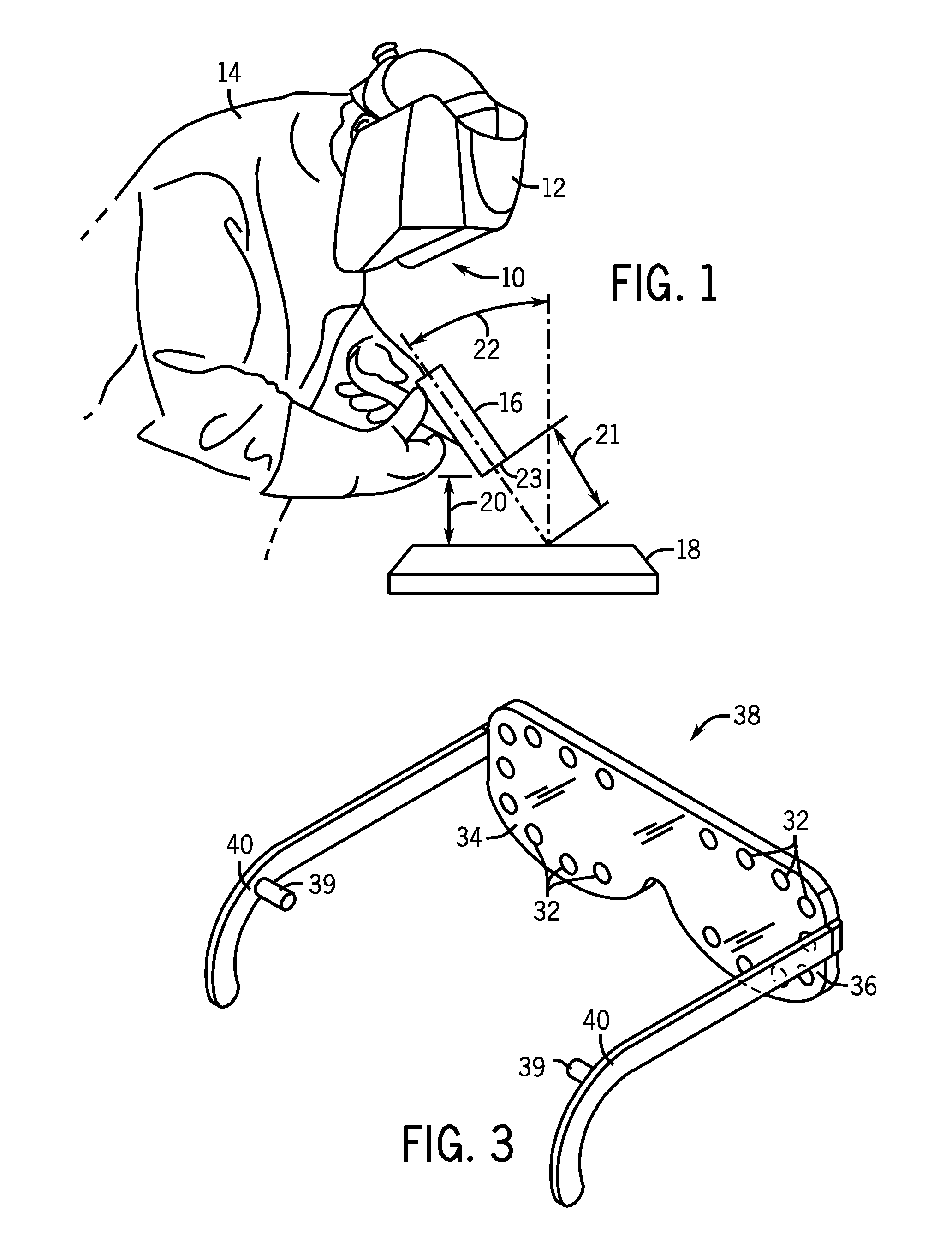
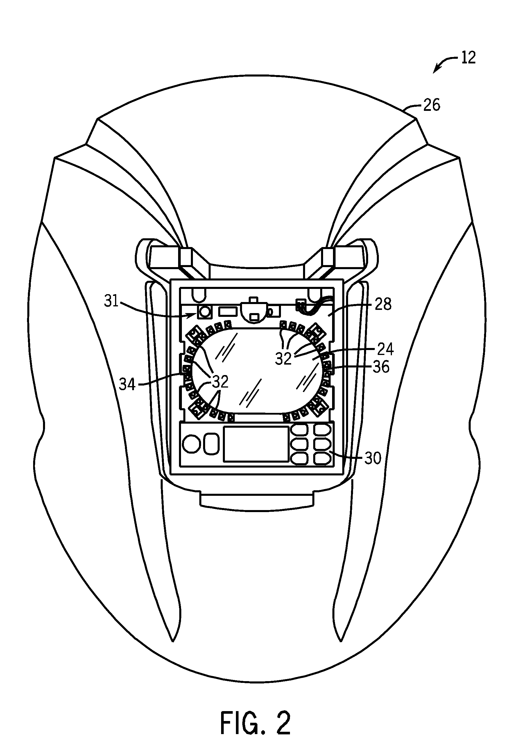
[0018]Apparatuses have been proposed that are used to monitor weld characteristics and provide feedback to the welding operator during welding. However, these traditional devices are generally not intuitive. For example, such devices generally require substantial knowledge of device programming and often require a welding operator to make indirect associations in order to interpret provided information such that proper adjustments can be made. Indeed, these traditional devices typically provide welding operators with an overload of difficult to decipher information. Thus, it is now recognized that there exists a needs for a device that will communicate in an intuitive fashion to a welding operator whether the torch angle and / or torch-to-workpiece distance during a weld falls within an optimal range. Accordingly, present embodiments are directed to systems and methods relating to real time weld characteristic communication in an intuitive fashion.

[0019]FIG. 1 illustrates a weld commu...


PUM

PropertyMeasurementUnit
angleaaaaaaaaaa
torch angleaaaaaaaaaa
tip-to-work distanceaaaaaaaaaa

Abstract

Methods and systems for transmitting a torch angle and / or a torch-to-workpiece distance error to a welding operator when these parameters are outside of a preset optimal range via real time visual and / or audio cues are provided. One embodiment of the present disclosure relates to weld characteristic communication via intuitive arrays of visual indicators located on the periphery of a lens, which indicate to the welding operator the direction and severity of the torch angle error. In one embodiment, audio cues, such as pulsed or continuous tones may be used to communicate torch-to-workpiece distance to the welding operator. In certain embodiments, vertical visual indicator arrays may be used to indicate additional weld or auxiliary information, such as battery charge state, torch speed and so forth, to the welding operator. All the components of the communication system may be located in or on the welding helmet or the components may be split between the helmet and a belt pack.

Description

CROSS REFERENCE TO RELATED APPLICATIONS[0001]This application is a Non-provisional Application of U.S. Provisional Application No. 61 / 143,261, filed Jan. 8, 2009 and U.S. Provisional Application No. 61 / 051,954, filed May 9, 2008, both entitled “Weld Characteristic Communication System for A Welding Helmet”, which are each herein incorporated by reference.BACKGROUND[0002]Embodiments of the present disclosure relate generally to weld communication systems, and more particularly, to systems and methods for intuitively communicating weld characteristics to a welding operator in real time.[0003]Welding is a process that has increasingly become ubiquitous in all industries. While such processes may be automated in certain contexts, a large number of applications continue to exist for manual welding operations, the success of which relies heavily on the proper use of a welding gun or torch by a welding operator. For instance, an improper torch angle can lead to spatter, improper penetratio...

Claims


Application Information

Patent Timeline
Patent Type & Authority Patents(United States)
IPC IPC(8): A61F9/06A61F9/04
CPCA61F9/06B23K9/322B23K9/0956
Inventor BECKER, WILLIAM JOSHUAPFEIFER, KYLE ANDREW
Owner ILLINOIS TOOL WORKS INC
Learn More