Battery state-of-charge estimator

a state-of-charge and battery technology, applied in the field of battery state-of-charge estimator, can solve the problems of low estimation precision of determined soc and reduced estimation precision of soc in soc estimation units, and achieve the effect of improving the accuracy of soc estimation

Inactive Publication Date: 2005-12-08
TOYOTA JIDOSHA KK
View PDF3 Cites 86 Cited by
  • Summary
  • Abstract
  • Description
  • Claims
  • Application Information

AI Technical Summary

Benefits of technology

[0008] The present invention was conceived in view of the above-described problems, and an object of the present invention is to provide a battery state-of-cha

Problems solved by technology

However, in the battery state-of-charge controller of Japanese Patent Laid-Open Publication No. 2000-166105, because the state of charge of the battery is determined based on the battery voltage from the voltage sensor when the current sensor is abnormal, the estimation precision of the determined SOC is low when the

Method used


Image

  • Battery state-of-charge estimator
  • Battery state-of-charge estimator
  • Battery state-of-charge estimator

Examples


first preferred embodiment

[Structure of a Battery State-of-Charge Estimator]

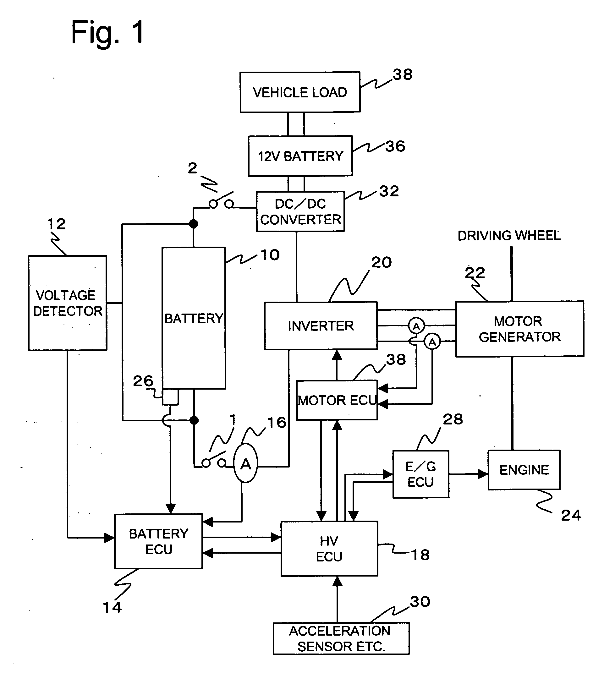
[0064]FIG. 1 is a block diagram showing a structure of a system in which a battery state-of-charge estimator according to a first preferred embodiment of the present invention is applied to a hybrid electric vehicle. A battery 10 is a battery pack in which a plurality of battery cells are connected in series and comprises, for example, cells of nickel hydrogen (Ni-MH) batteries and lithium ionbatteries.

[0065] A voltage of the battery 10 is measured by a voltage detector 12 which is a voltage detector unit and the measured voltage is supplied to a battery ECU 14. A current sensor 16 which is a current detector unit for detecting a current of the battery is also connected to the battery ECU 14 such that the detected battery current value is supplied to the battery ECU 14. A thermometer 26 for detecting a temperature of the battery is provided for the battery 10 and a value of the detected battery temperature is also supplied to the b...

second preferred embodiment

[Structure of Battery State-of-Charge Estimator]

[0077] A battery state-of-charge estimator according to the second preferred embodiment has a structure identical to that in the first preferred embodiment of the present invention described above, and the elements identical to those in the first preferred embodiment will be assigned the same reference numerals and will not be described again.

[Estimation of State of Charge of Battery]

[0078] An example first SOC estimator unit according to the present invention is operated as shown in FIG. 4 in the battery ECU 14 shown in FIG. 1.

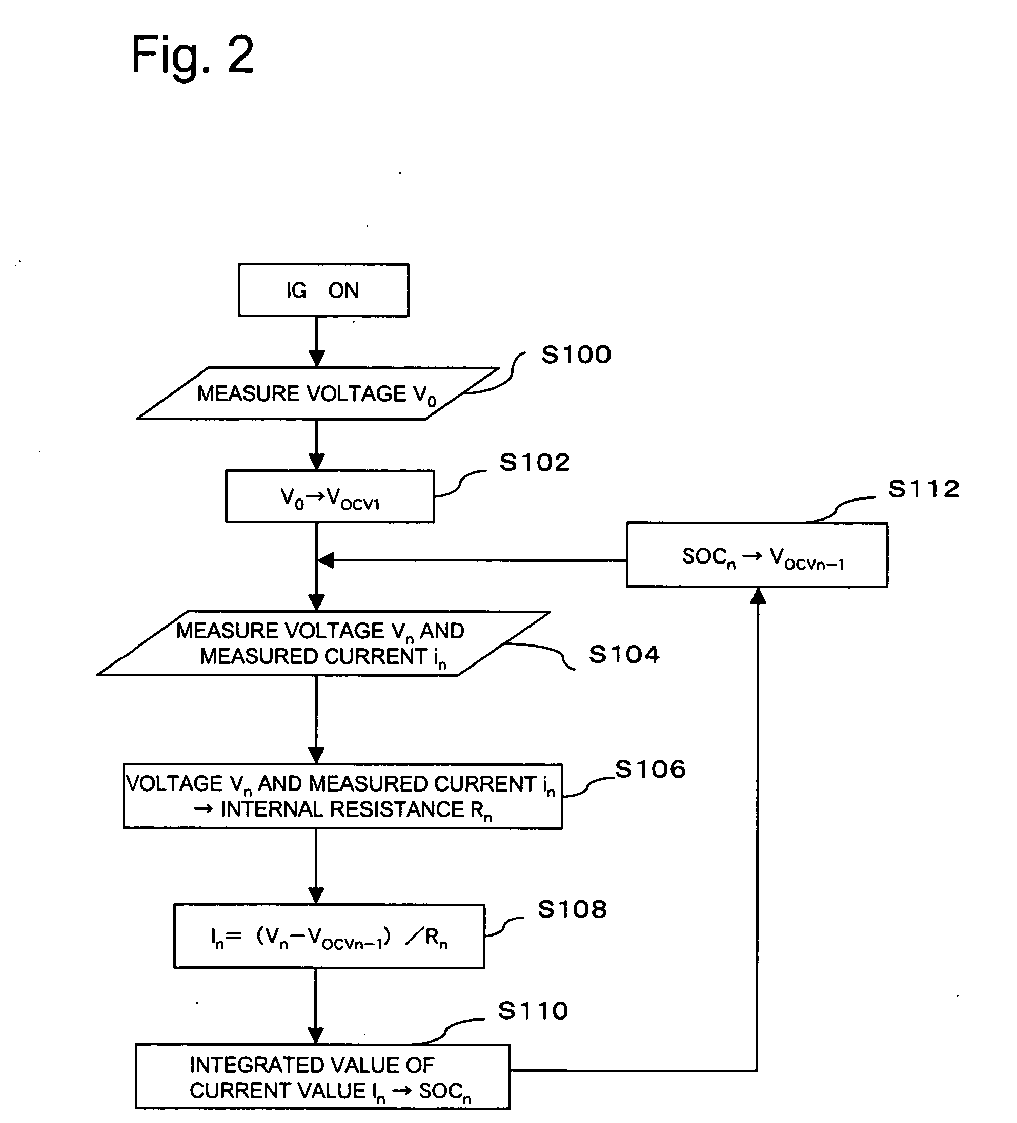
[0079] When IG is switched ON, the voltage detector 12 measures an initial battery voltage V0 before the relays 1 and 2 are switched on (S200). Then, the initial battery voltage V0 is set as an open voltage Vocv1 (S202). The voltage detector 12 measures a present battery voltage Vn (n is 1˜n and does not include 0; similarly in the following description) under a loaded state after the relays 1 and 2 are swit...

third preferred embodiment

[Structure of the Battery State-of-Charge Estimator]

[0083] A battery state-of-charge estimator according to the present embodiment has a structure identical to that of the first and second preferred embodiments described above except that the battery state-of-charge estimator according to the present embodiment does not have a current sensor 16. The elements identical to those in the first and second preferred embodiments are assigned the same reference numerals and will not be described again.

[Estimation of State of Charge of the Battery]

[0084] An operation of another example first SOC estimator unit according to the present invention in a battery ECU 14 as shown in FIG. 5 will now be described referring to FIG. 6.

[0085] When IG is switched ON, the voltage detector 12 measures an initial battery voltage V0 before the relay 2 is switched on (S300). Then, the initial battery voltage V0 is set as an open voltage Vocv1 (S302). The voltage detector 12 measures a present battery volt...


PUM


Abstract

A battery ECU estimates the SOC by integrating the battery current measured by a current sensor, and the battery voltage Vn is measured by a voltage sensor and the battery temperature Tn is measured by a thermometer if the fluctuation of the charging/discharging current is great. If the number m of estimations of SOCn is m<10, m is incremented. The battery internal resistance Rn is estimated from the measured battery temperature Tn by using a correlation map showing the correlation between the previously stored battery temperature T and the battery internal resistance R. An estimation charging/discharging current In is determined using the measured battery voltage Vn, the battery open voltage Vocvn−1 determined on the basis of the previously estimated charged state, and the estimated battery internal resistance Rn. The SOCn is estimated by integrating the estimated charging/discharging current In. If the number m of estimations of the SOCn is m=10, the number m of estimations is changed to 0. The charging/discharging current in is measured by a current sensor. The battery internal resistance Rn is calculated from the battery voltage Vn and the charging/discharging current in. The battery temperature Tn is also measured, and the T-R correlation map is corrected.

Description

TECHNICAL FIELD [0001] The present invention relates to a battery state-of-charge estimator which estimates the state of charge of a battery equipped to a vehicle. BACKGROUND ART [0002] Conventionally, a secondary cell (that is, a battery such as a nickel hydrogen battery or a lithium ion battery) for driving a motor in hybrid electric vehicles having a power generator for generating power by driving and regeneration by an engine and a motor which is operated with power from the battery for driving a driving wheel and in electric vehicles including the hybrid vehicles. [0003] As an indication of a state of charge of the battery, a measure known as SOC (state of charge) is used, in which an SOC of 100% represents a fully charged state and an SOC of 0% represents a state in which the amount of charging is zero. In addition, there is a one-to-one correspondence between an open voltage Vocv and the SOC for a battery. Therefore, it is possible to calculate an SOC corresponding to an open...

Claims


Application Information

Patent Timeline
IPC IPC(8): B60L3/00G01R31/36H01M10/48H02J7/00
CPCG01R31/3648G01R31/3624G01R31/3842Y02E60/10G01R31/389H02J7/0048H01M10/486
Inventor MITSUI, MASAHIKONAKAYAMA, YOSHIYUKI
Owner TOYOTA JIDOSHA KK
Why Eureka
Try Eureka