Magazine for air gun having rotary clip

a technology of air gun and magazine, which is applied in the direction of compressed gas guns, white arms/cold weapons, weapons, etc., can solve the problem of not rotating the rotary clip, and achieve the effect of reducing the failure rate of air guns, reducing the occurrence of stopped rotation, and improving usability for users

Active Publication Date: 2011-06-21
MARUZEN
View PDF46 Cites 19 Cited by
  • Summary
  • Abstract
  • Description
  • Claims
  • Application Information

AI Technical Summary

Benefits of technology

[0016]Therefore, for an air gun using a magazine according to the present invention, occurrence of stopped rotation is reduced when the rotary clip rotates, and the air gun is used without problems, thus improving usability for users.
[0017]The failure rate of an air gun can be reduced because accidents where a rotary clip or a mechanism for rotating a rotary clip are damaged because a trigger is pulled forcedly when the rotary clip does not rotate can be prevented.

Problems solved by technology

Additionally, when the magazine main body is removed from the magazine retention part and a shooter loads a pellet into each bore and rotates the magazine by one bore after loading a pellet into a bore, in the same manner, if a pellet projects from the hollow tubular end surface of the bore, the projecting pellet gets stuck with the end side of the attachment wall of the magazine main body and the rotary clip does not rotate, which is also a problem.

Method used


Image

  • Magazine for air gun having rotary clip
  • Magazine for air gun having rotary clip
  • Magazine for air gun having rotary clip

Examples


first embodiment

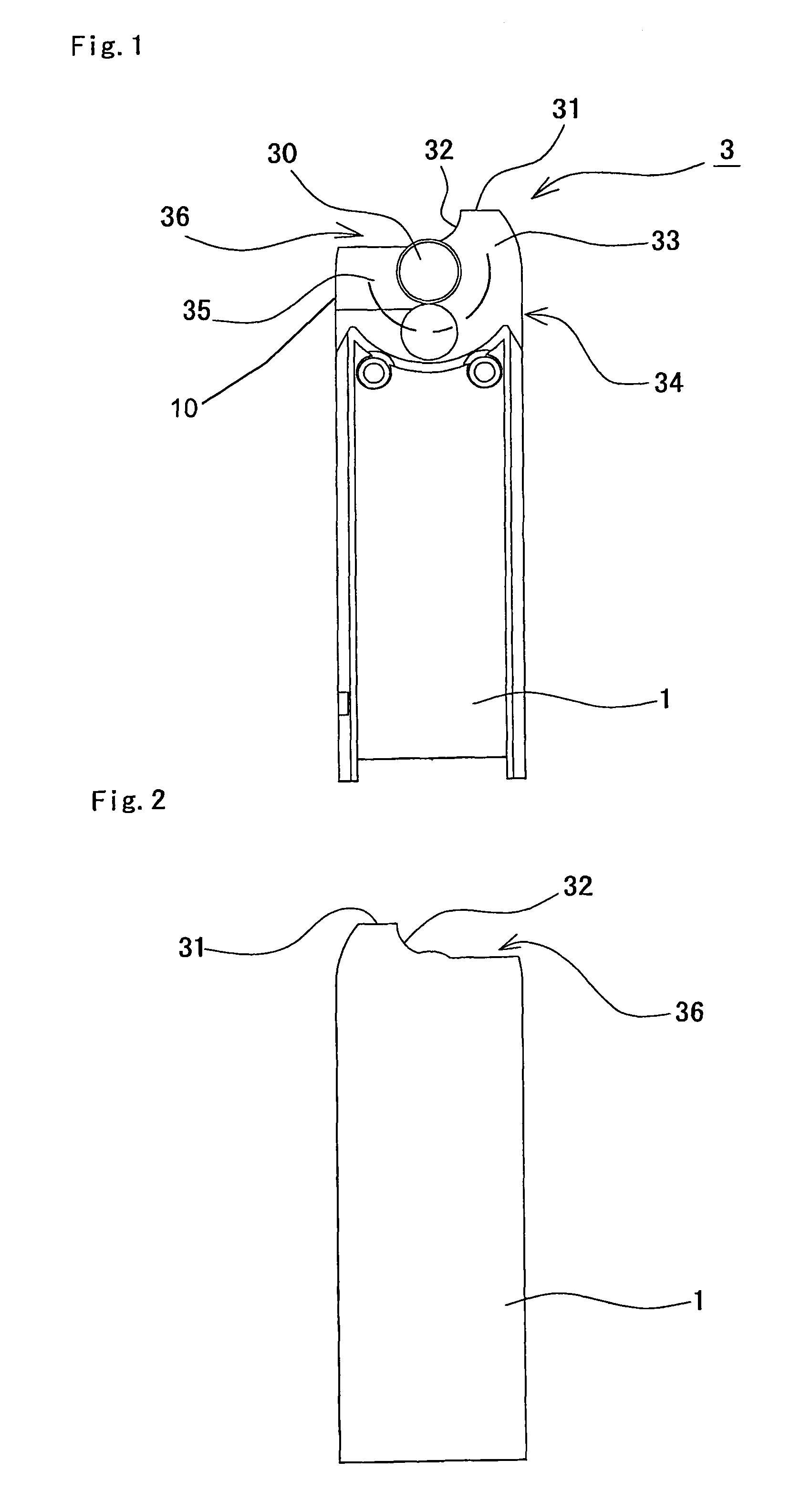
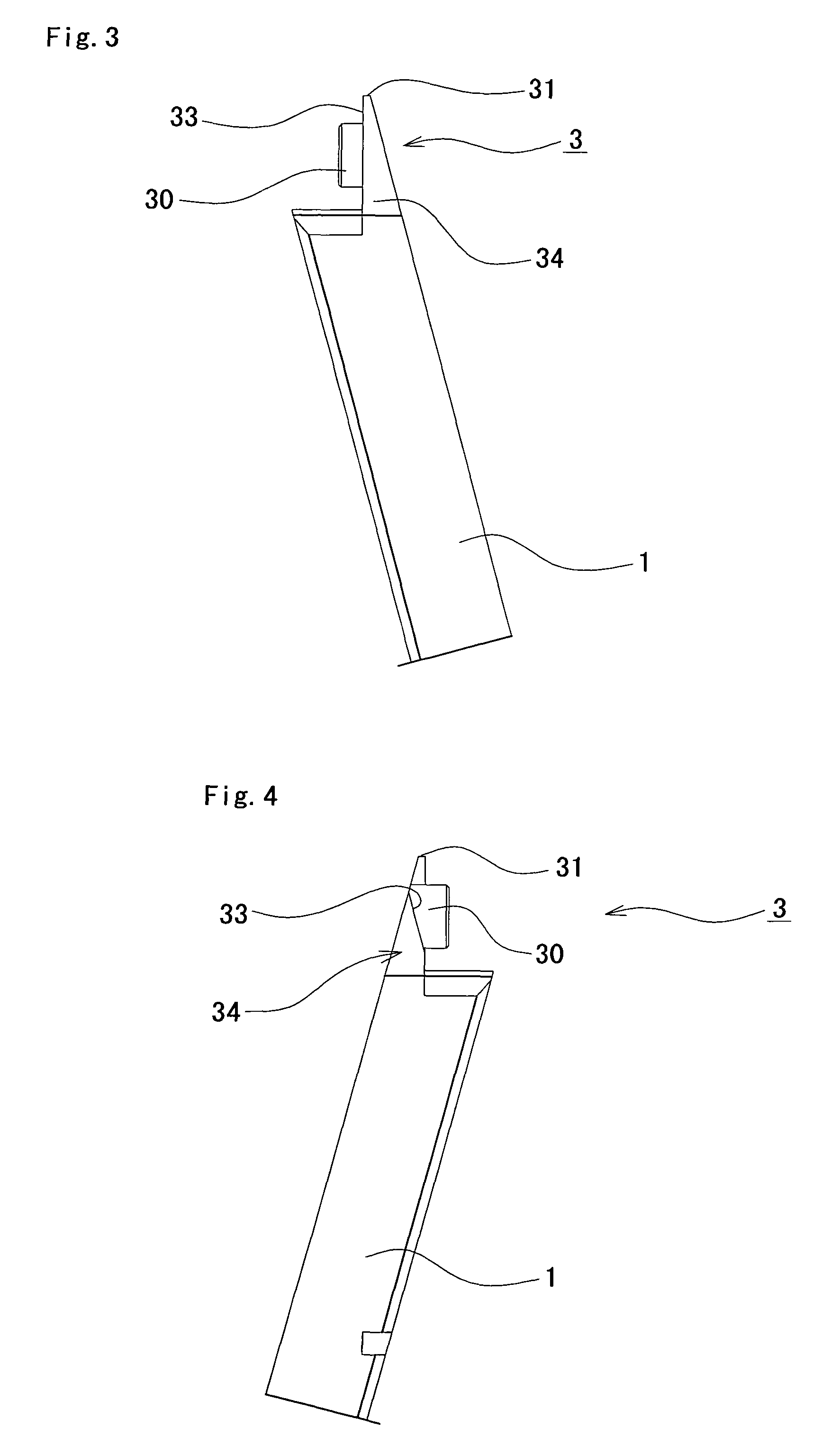
[0046]In the first embodiment from FIGS. 1 to 4, the clip opposing wall surface 33 gradually departs from the cylindrical end surface of opposing rotary clip 2 towards the end side of the clip attachment wall 34 within the whole range up to the left side part 10 including the range 35 of the rotational opposing surface positioned between the hit pin concave part 32 and the side part 10 (left side of the magazine main body 1 according to this embodiment) in the rotational direction of the rotary clip 2.

second embodiment

[0047]In the second embodiment from FIGS. 5 to 8, the clip opposing wall surface 33 gradually moves away from the cylindrical end surface of the opposing rotary clip 2 towards the end side of the clip attachment wall 34 within the range 35 of the rotational opposing surface positioned from the hit pin concave 32 to the side surface part 10 (the left surface of the magazine main body 1 in this embodiment) in the rotational direction of the rotary clip 2. The parallel surface 37 of the side part which does not oppose the cylindrical surface of the rotary clip near the left surface part 10 keeps parallel to the cylindrical end surface of the rotary clip 2.

[0048]In the embodiment common to them, the thickness of the attachment wall 34 of the rotary clip attachment part 3 gets gradually thinner closer to the end side within the range 35 of the rotational opposing face positioned between the hit pin concave 32 and a side surface part 10 in the rotational direction of the rotary clip.

[0049...


PUM


Abstract

There has been a problem that a projected part of a rear part of a pellet gets stuck with an end side of an attachment wall and rotation is interrupted when a rotary clip moves from a hit pin concave to an end side (i.e., attachment wall) of a magazine main body if the rear end of a pellet in a bore projects from a bore. In order to resolve the problem, there is proposed a magazine main body 1 and a magazine main body 1 having a rotary clip 2 rotatably attached to a rotary clip attachment part 3 of a magazine main body 1 characterized in that a clip opposing wall surface 33 of an attachment wall 34 of a clip opposing wall surface 33 gradually moves away from a cylindrical end surface of opposing rotary clip 2 towards an end side 31 of an attachment wall 34 within a range 35 of a rotational opposing surface positioned between a hit pin concave 32 and a side surface part 10 in the rotational direction of rotary clip 2.

Description

BACKGROUND OF THE INVENTION[0001]1. Field of the Invention[0002]This invention relates to a magazine of an air gun (air pistol), and more specifically relates to a magazine of air gun with a rotary clip (rotary magazine).[0003]2. Description of the Related Art[0004]A magazine of an air gun consists of a substantially rectangular magazine main body with a rotary clip which is a magazine part at either one end or at both ends. This magazine main body is inserted into and attached to a magazine retention part which is a cavity of the air gun main body.[0005]FIGS. 16 through 23, which are fragmentary views, show a conventional magazine main body 100 having a clip rotational axis 101 to which a rotary clip 200 is rotatably attached, and a rotary clip attachment part 105 having an attachment wall 103 including a opposing wall 102 on which the clip rotational axis 101 is provided, formed on at least one end. A hit pin concave part 104 is formed on an upper and lower end of the rotary clip ...

Claims


Application Information

Patent Timeline
Patent Type & Authority Patents(United States)
IPC IPC(8): F41A9/61F41B11/54
CPCF41B11/54F41A9/73
Inventor MAEDA, TETSUO
Owner MARUZEN
Why Eureka
Try Eureka