Servo motor and rotor thereof

a servo motor and rotor technology, applied in the direction of dynamo-electric machines, electrical apparatus, magnetic circuits, etc., can solve the problems of affecting positional control, affecting positional control, and affecting the shape of magnets, so as to reduce the torque of the servo motor and improve the shape of the magnets

Inactive Publication Date: 2011-06-21
JOHNSON ELECTRIC SA
View PDF7 Cites 4 Cited by
  • Summary
  • Abstract
  • Description
  • Claims
  • Application Information

AI Technical Summary

Benefits of technology

[0006]A servo motor with reduced cogging is achieved in the present invention by using a rotor having permanent magnets arranged and adapted to reduce cogging.
[0013]The advantages of some embodiments of the present invention include that by improving the shape of the magnets, the magnetic flux waveform can be made to be very similar to a sine wave. Also, by dividing the rotor poles or the rotor into two or more portions in the axial direction, and staggering adjacent portions by a predetermined mechanical angle in the circumferential direction, the fundamental wave composition of the cogging torque can be reduced or eliminated, thus reducing the cogging torque of the motor.

Problems solved by technology

The greater the cogging torque, the greater this tendency to snap.
Cogging is particularly noticeable in low speed operation as the rotor tries to snap or jump from one prepared position to the next.
It also affects positional control as the rotor becomes unstable between the preferred angular positions.
Generally speaking, in a permanent magnet motor, cogging torque usually is the basic cause of vibration and noise and adversely affects control precision.

Method used


Image

  • Servo motor and rotor thereof
  • Servo motor and rotor thereof
  • Servo motor and rotor thereof

Examples


Embodiment Construction

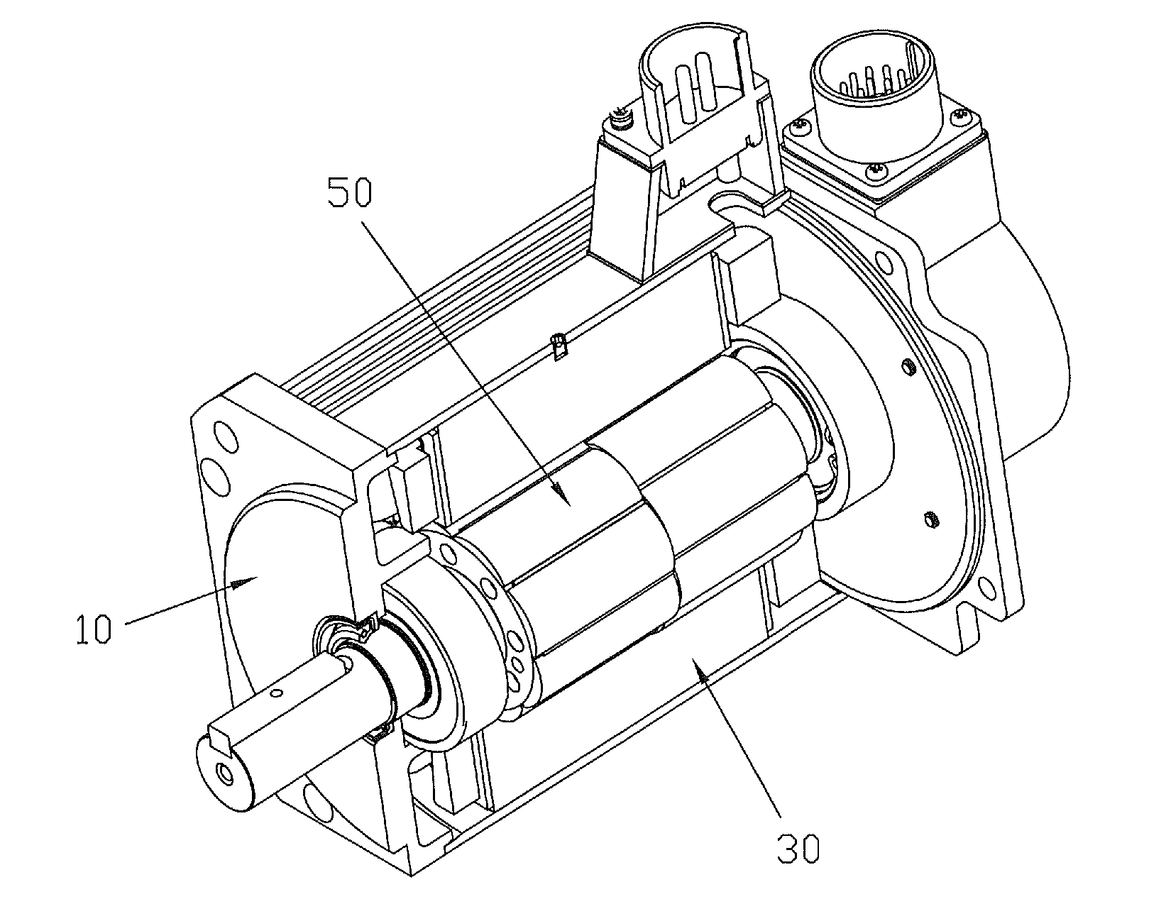
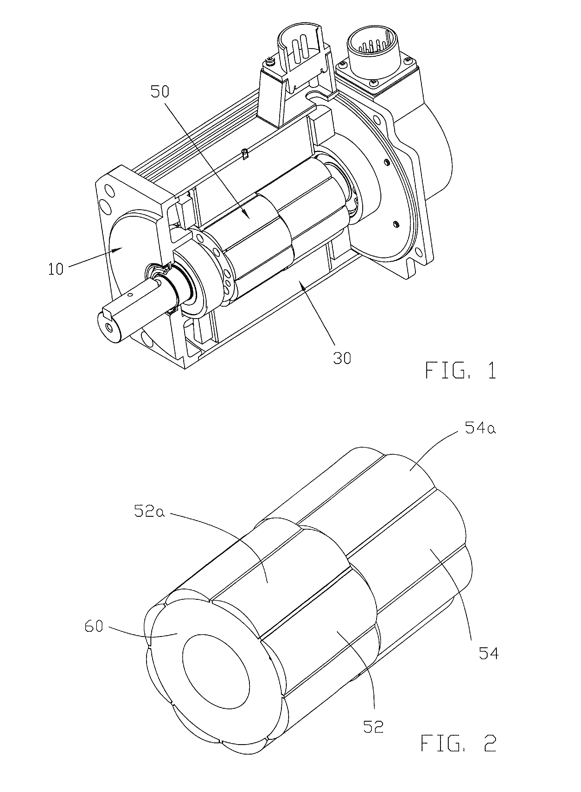
[0023]As shown in FIG. 1, the servo motor of the preferred embodiment of the present invention has a casing 10, a stator 30 and a rotor 50 disposed within an inner cavity of the stator.

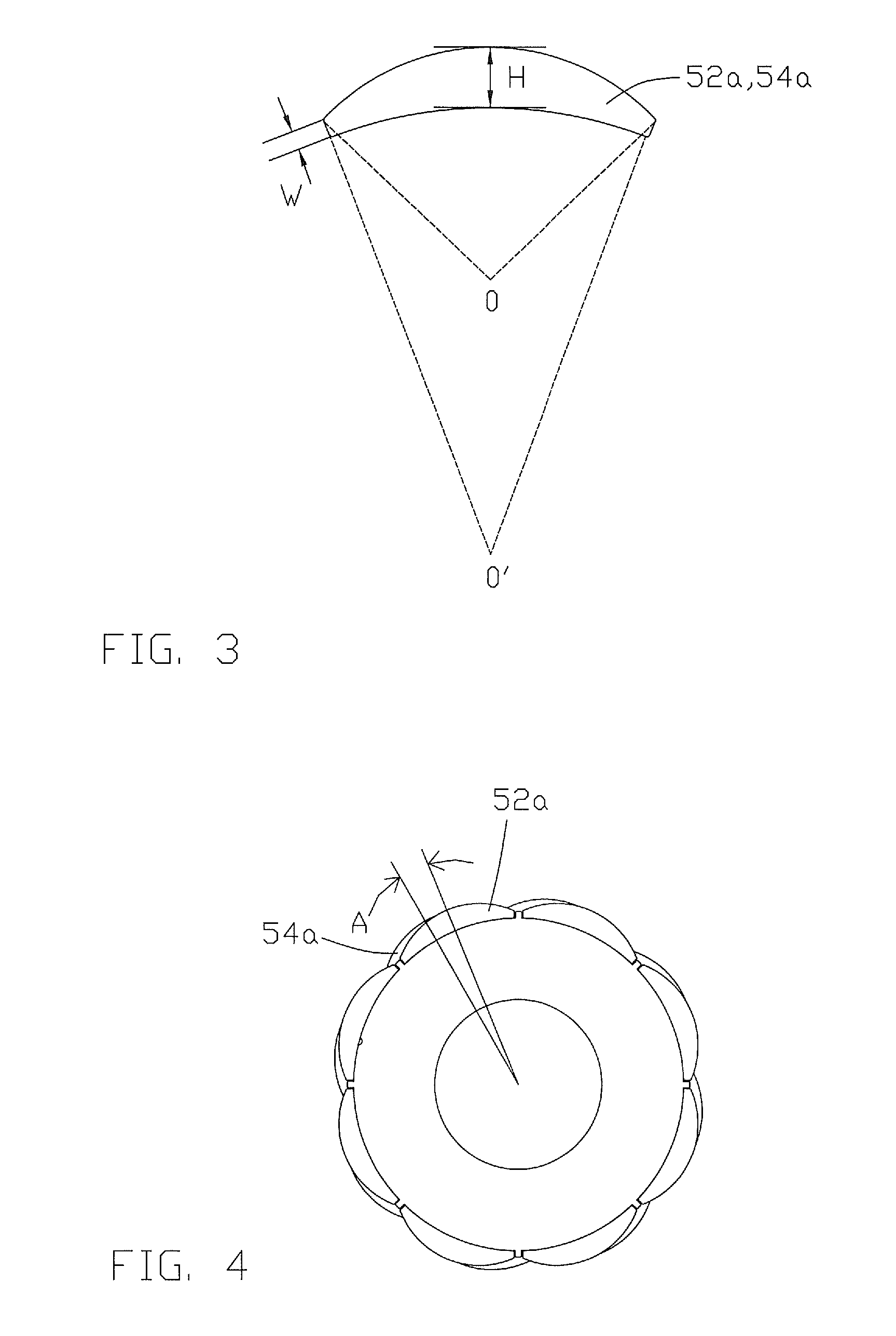
[0024]FIG. 2 illustrates a rotor with the motor shat removed for clarity. The rotor 50 comprises a rotor core 60 and a plurality of magnets covering a radially outer surface of the core 60. The magnets form a number of rotor poles which extend axially of the rotor. Each magnet has a center and two longitudinal edges which confront or face magnets of adjacent rotor poles, usually across a small gap. Each rotor pole has two or more magnets 52a, 54a, arranged axially. The magnets of each rotor pole are offset or staggered by a predetermined mechanical angle A, such that the rotor may be divided into a plurality of rotor portions 52, 54, in which the centers of the magnets of adjacent portions are offset or staggered in the circumferential direction of the core 60 to produce a skewing of the resultant mag...


PUM


Abstract

A servo motor, comprising a stator and a rotor disposed within the stator. The rotor has a core and magnets, covering the periphery of the core, forming a plurality of axially extending rotor poles. The rotor poles comprise a plurality of the magnets arranged axially, and the centers of adjacent magnets of a rotor pole are staggered by a mechanical angle in the circumferential direction of the rotor.

Description

CROSS REFERENCE TO RELATED APPLICATIONS[0001]This non-provisional patent application claims priority under 35 U.S.C. §119(a) from Patent Application No. 200810066916.1 filed in The People's Republic of China on Apr. 28, 2008, the disclosure of which is incorporated herein by reference.FIELD OF THE INVENTION[0002]This invention relates to an electric motor and in particular, to a rotor for a servo motor which can reduce cogging torque.BACKGROUND OF THE INVENTION[0003]With the development of power electronics, servo motors have become widely used in many applications. The servo motor, as a special type of motor, has a working principle in electrical signals are transformed into angular displacement or angular velocity of the output shaft. The servo motor is easy to control, has a small volume, is relatively light weight with high output power and torque.[0004]FIG. 7 illustrates a rotor structure of a conventional servo motor, and FIG. 8 is a graph of cogging torque verses the mechanic...

Claims


Application Information

Patent Timeline
Patent Type & Authority Patents(United States)
IPC IPC(8): H02K21/12
CPCH02K1/278H02K2201/06H02K29/03H02K16/02H02K1/2781
Inventor CHAI, JI DONGLIU, BAO TINGLI, WEN LIANGSHAO, ZHI DUAN
Owner JOHNSON ELECTRIC SA
Why Eureka
Try Eureka