Magnetic member, motor device, magnetizing method, and storage device

a technology of magnetic members and permanent magnets, applied in the direction of rotating magnets, synchronous machines with stationary armatures, stator/rotor bodies, etc., can solve the problem of newly occurring cogging, and achieve excellent magnetic properties and reduce cogging of small permanent magnets.

Inactive Publication Date: 2010-10-14
TAKEHARA ISAMU +2
View PDF6 Cites 3 Cited by
  • Summary
  • Abstract
  • Description
  • Claims
  • Application Information

AI Technical Summary

Benefits of technology

[0029]According to the present invention, cogging of a small permanent magnet can be reduced while maintaining magnetization properties excellent.

Problems solved by technology

Although a small permanent magnet has become possible to be magnetized excellently according to the arts disclosed in Patent documents 1 and 2, the problem of cogging has newly occurred with the development of thinner permanent magnets.

Method used


Image

  • Magnetic member, motor device, magnetizing method, and storage device
  • Magnetic member, motor device, magnetizing method, and storage device
  • Magnetic member, motor device, magnetizing method, and storage device

Examples


Embodiment Construction

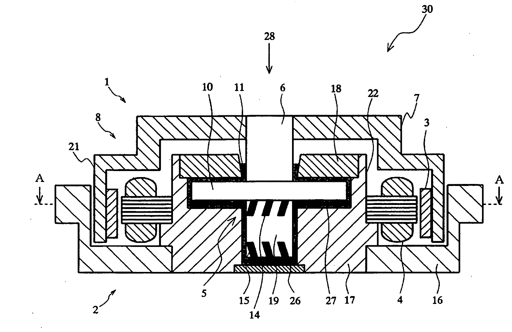
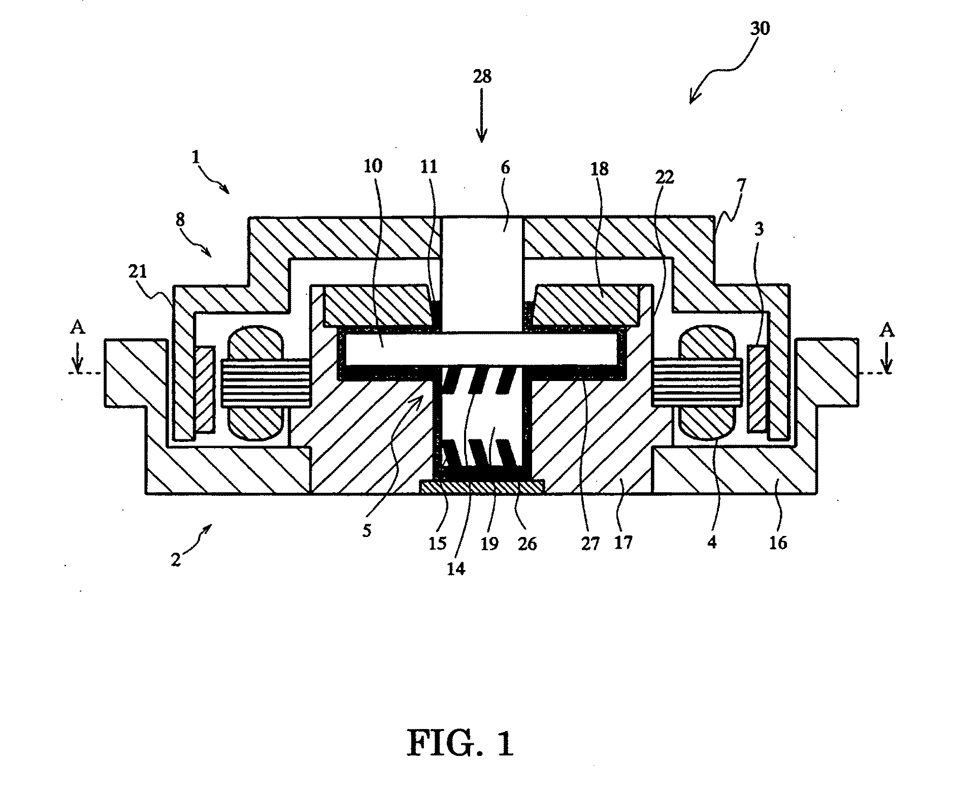
[0042]Hereafter, a suitable embodiment of the present invention is explained in detail.

(1) An Outline of the Embodiment

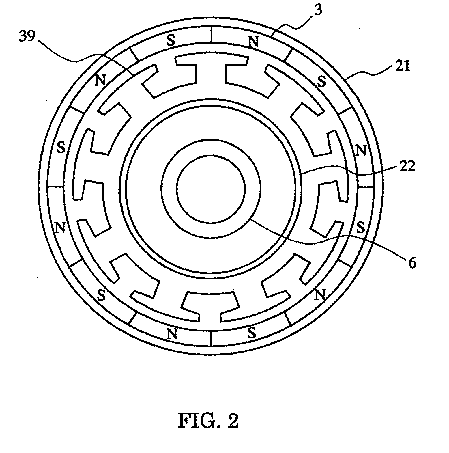
[0043]When the inner diameter of the permanent magnetic membrane is D, the pitch per one magnetic pole is P and the phase number of the alternating current is M, an excellent permanent magnet with low cogging is obtained, by setting D to 20 mm or less, and setting the wall thickness of the permanent magnet t in the range described by the following relation (4).

πD / (0.75PM−π)t≦πD / (0.5PM−π)  (4)

[0044]In this embodiment, an outer rotor type permanent magnet is explained, but formula (4) is applicable also to an inner rotor type permanent magnet.

[0045]Moreover, in this embodiment, the formula can be desirably applied to a small permanent magnet with an outer diameter of 20 mm or less.

[0046]Furthermore, in this embodiment, a Sm—Co (samarium-cobalt) based magnetic material is adopted as a magnetic material.

[0047]Generally, as a wall thickness of the permanent magnet is mad...


PUM

PropertyMeasurementUnit
diameteraaaaaaaaaa
outer diameteraaaaaaaaaa
outer diametersaaaaaaaaaa

Abstract

A method of magnetizing a magnetic member for a rotor of a motor device. The magnetic member has a thickness t in the radial direction of the magnetic member satisfying the relation πD / (0.75MP−π)<t≦πD / (0.5MP−π), where D represents an inner diameter of the magnetic member having a value of 20 mm or less, P represents the number of magnetic poles, and M represents the number of alternating current phases for driving the motor device. The magnetic member is magnetized unidirectionally in the radial direction of the magnetic member. Thereafter, the unidirectionally magnetized magnetic member is magnetized in partitions at regular intervals in the radial direction so that a magnetization direction of the magnetic member is reversed and the magnetic poles are arranged at regular intervals in a circumferential direction.

Description

BACKGROUND OF THE INVENTION[0001]1. Field of the Invention[0002]The present invention relates to a magnetic member, a motor device, a magnetizing method and a storage device, which are, for example, used for a small hard disk drive.[0003]2. Description of the Related Art[0004]In recent years, miniaturization of disc storage devices, such as hard disk drives and optical disk drives, are progressing rapidly, and devices with disc outer diameters of 1 inch or less are beginning to spread rapidly.[0005]A small disc storage device is used for portable instruments, such as, for example, portable sound reproduction devices, digital cameras and cellular phones as well as for stationary devices, such as personal computers, office automation equipments and home information appliances.[0006]Disc driving motors used in disc storage devices include an outer rotor type and an inner rotor type, but the outer rotor type suitable for miniaturization is mainly in use.[0007]The outer rotor type motor ...

Claims


Application Information

Patent Timeline
Patent Type & Authority Applications(United States)
IPC IPC(8): H02K21/22H02K15/03
CPCH02K1/2786Y10T29/49012H02K21/22H02K15/03H02K1/2791
Inventor TAKEHARA, ISAMUKINOSHITA, SHINJIGOTOH, HIROMITSU
Owner TAKEHARA ISAMU
Why Eureka
Try Eureka