
Method and apparatus for time-of-flight mass spectrometry

a mass spectrometry and time-of-flight technology, applied in the field of time-of-flight mass spectrometry, can solve the problems of deterioration of sensitivity and mass resolution, deviation of the number of turns at the detected surface from the correct number, and complicated equipment, so as to prolong the flight time and maintain the time focusing properties

Active Publication Date: 2007-08-23
JEOL LTD
View PDF3 Cites 49 Cited by
  • Summary
  • Abstract
  • Description
  • Claims
  • Application Information

AI Technical Summary

Benefits of technology

[0037] Accordingly, it is a first object of the present invention to provide a TOF-MS which improves focusing of revolving ions in the orthogonal direction and which permits connection with an orthogonal-acceleration ion source for improvement of sensitivity.
[0127] (29) According to the twenty-ninth embodiment of the present invention, the multi-turn TOF-MS or helical-trajectory TOF-MS according to any one of the first through twenty-eighth embodiments adopts the ion optical system that can fully satisfy the spatial and time focusing conditions whenever a revolution is made, regardless of initial position, initial angle, or initial energy. The flight time can be prolonged while maintaining the time focusing properties.

Problems solved by technology

This leads to deteriorations of the sensitivity and mass resolution.
Furthermore, if the velocities are widely distributed in the orthogonal direction, there is the possibility that the number of turns at the detected surface deviates from the correct number.
If the number of deflectors is increased, however, more elements must be adjusted, complicating the equipment.
Consequently, the aforementioned problems cannot be solved.

Method used


Image

  • Method and apparatus for time-of-flight mass spectrometry
  • Method and apparatus for time-of-flight mass spectrometry
  • Method and apparatus for time-of-flight mass spectrometry

Examples


fourth embodiment

[0192]FIG. 9 is a diagram illustrating the operation of the fourth embodiment of the present invention. Like components are indicated by like reference numerals in both FIGS. 8 and 9. This embodiment has the configuration shown in FIG. 8. In addition, ions entered from the ion reservoir 32 are further deflected to permit angular adjustment. In the figure, a deflector 50 is mounted to adjust the angle of the entered ions. The deflector operates to match the tilt angle of the ions to the tilt angle of the laminated toroidal electrodes in a case where the tilt angle of the laminated toroidal electrodes is different from the tilt of the ejected ions.

[0193] In the apparatus constructed in this way, ions are created by the continuous ion source 40 and transported into the ion reservoir 32 perpendicularly to the direction of acceleration. The ions stored in the reservoir 32 are applied with a pulsed voltage from the electrodes 30 and 31. At this time, the ions are inevitably traveled obli...

second embodiment

[0200]FIG. 13 is a diagram illustrating a first embodiment of the second aspect of the present invention. Like components are indicated by like reference numerals in both FIGS. 10 and 13. (a) is a view of the apparatus as viewed from the Y-direction. (b) is a view of the apparatus as viewed from the direction of the arrow of the “lower view” in (a). A sample 30 is mixed into a matrix (such as liquid or crystalline compound or metal powder), dissolved, solidified, and placed onto a sample plate 20 (see FIG. 11). A lens 2, a mirror 25, and a CCD camera 27 are disposed to permit observation of the state of the sample 30.

[0201] Laser light is directed at the sample 30 via the lens 1 and mirror 24 to vaporize or ionize the sample. The generated ions are accelerated by the voltage applied to the accelerating electrodes 21 and 22 and introduced into a helical-trajectory TOF-MS. In a general TOF-MS, it is necessary that the produced ions be pulsed by a pulsed voltage for measurement of fli...


PUM


Abstract

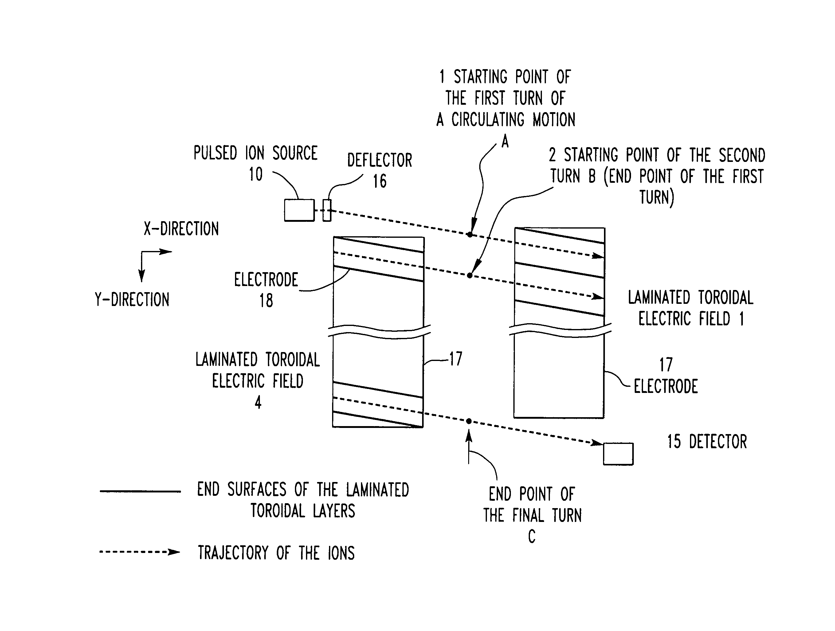
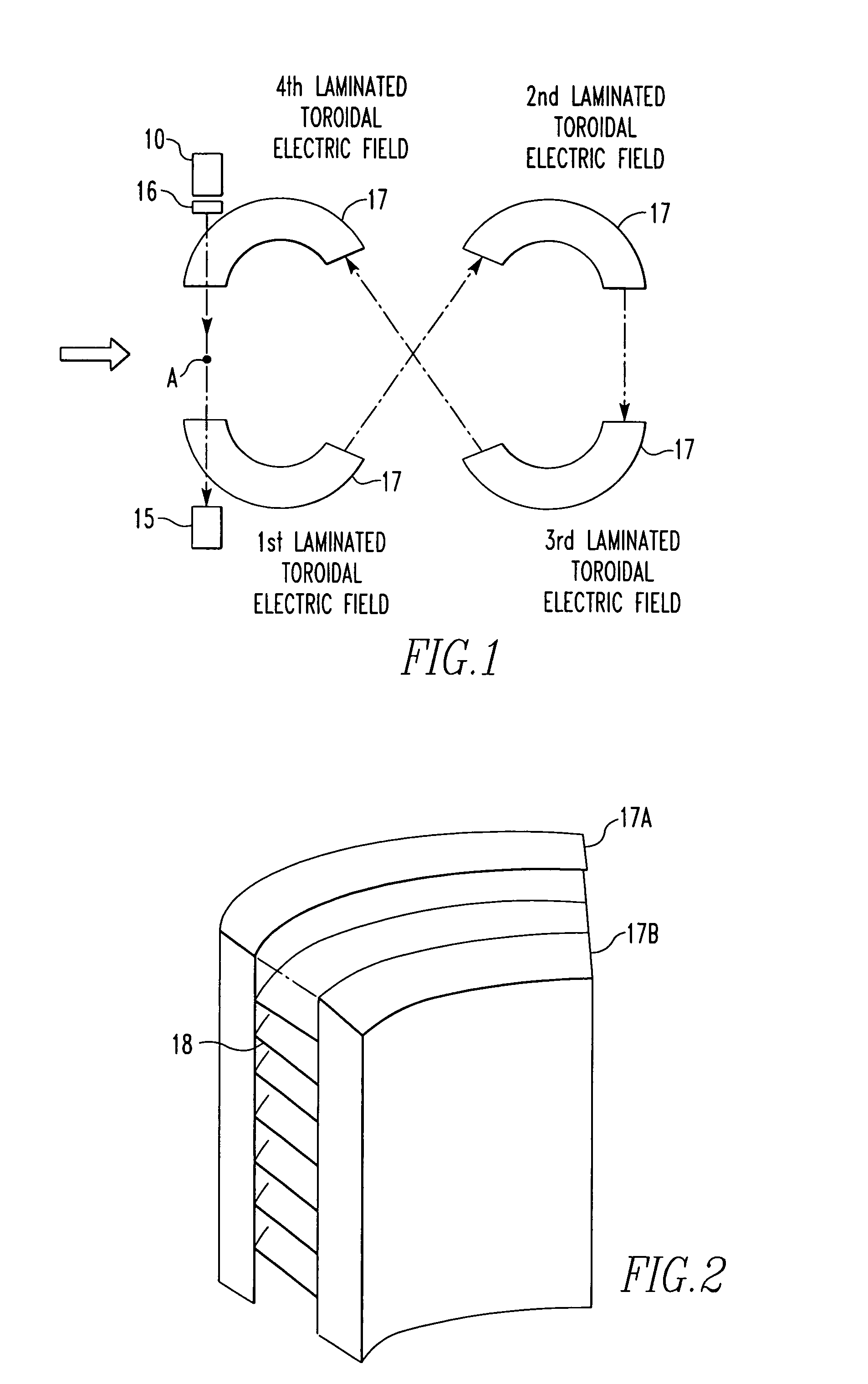
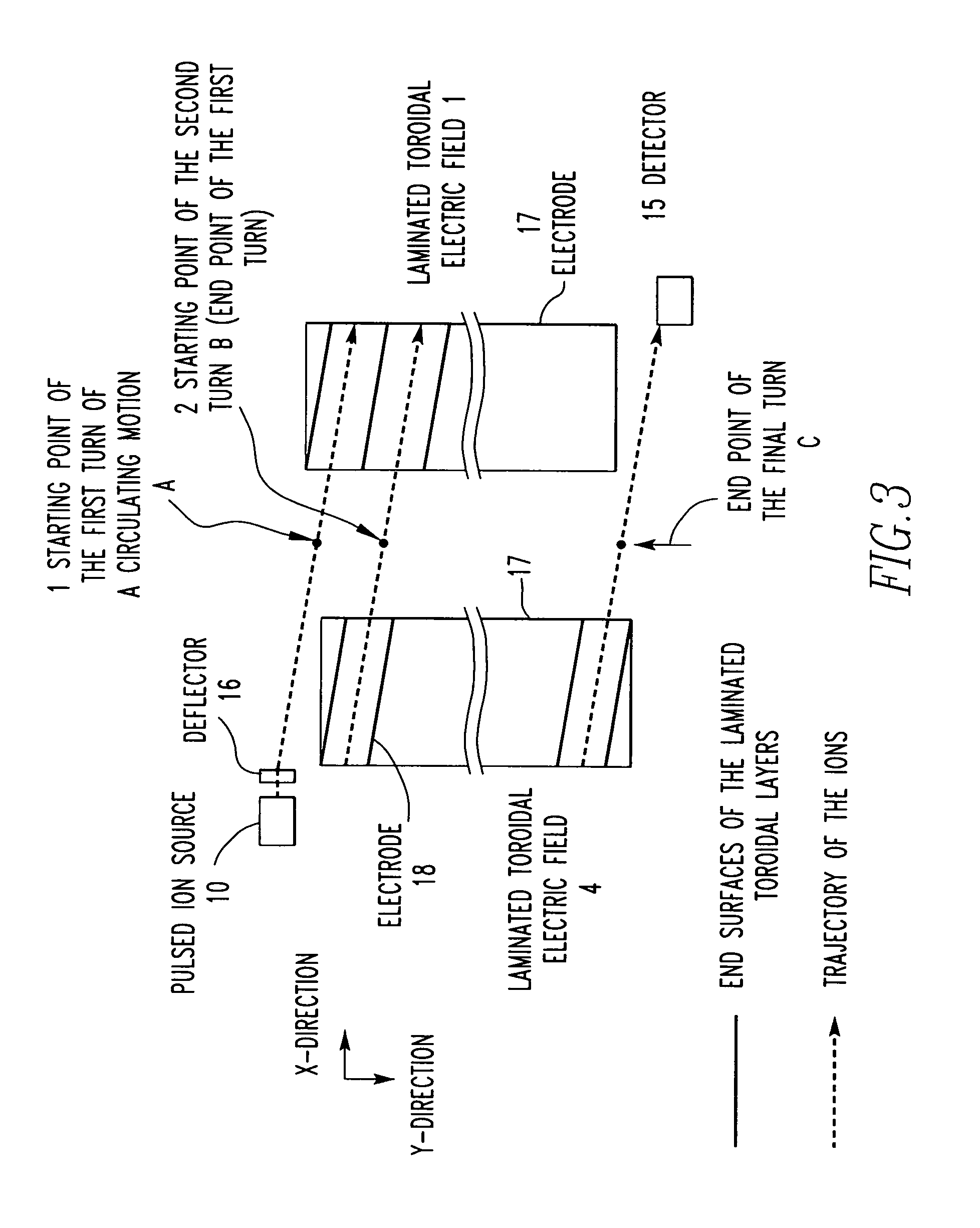
A method and apparatus for time-of-flight (TOF) mass spectrometry. The apparatus improves the ion focusing properties in an orthogonal direction and permits connection with an orthogonal-acceleration ion source for improvement of sensitivity. The apparatus comprises an ion source for emitting ions in a pulsed manner, an analyzer for realizing a helical trajectory, and a detector for detecting the ions. The analyzer is composed of plural laminated toroidal electric fields to realize the helical trajectory.

Description

TECHNICAL FIELD [0001] The present invention relates to a method and apparatus for time-of-flight (TOF) mass spectrometry. BACKGROUND [0002] (a) Time-of-Flight Mass Spectrometer (TOF-MS) [0003] A TOF-MS finds the mass-to-charge ratio (m / z) of sample ions by measuring the time taken for the ions to travel a given distance, based on the principle that the sample ions accelerated with a constant acceleration voltage have a flight velocity corresponding to the m / z. The principle of operation of the TOF-MS is illustrated in FIG. 26. The illustrated spectrometer has a pulsed ion source 5 composed of an ion generation portion 6 and a pulsed voltage generator 7. [0004] Ions i present within the electric field are accelerated by the acceleration voltage generator 7. The accelerating voltage is a pulsed voltage. Acceleration caused by the acceleration voltage and time measurement performed by an ion detector system (including detector 9) are synchronized. Simultaneously with the acceleration ...

Claims


Application Information

Patent Timeline
IPC IPC(8): H01J49/00G01N27/62H01J49/06H01J49/40
CPCH01J49/408H01J49/164
Inventor SATO, TAKAYATOYODA, MICHISATOISHIHARA, MORIO
Owner JEOL LTD
Learn More