

Multi-rotor plant protection unmanned aerial vehicle
A plant protection drone and multi-rotor technology, applied in the field of drones, can solve the problems of limited payload capacity, large overall structure size, high design and maintenance costs, and achieve effective payload enhancement, overall structure simplification, and flight time. long lasting effect
- Summary
- Abstract
- Description
- Claims
- Application Information
AI Technical Summary
Problems solved by technology
Method used
Image

Examples
Embodiment 1
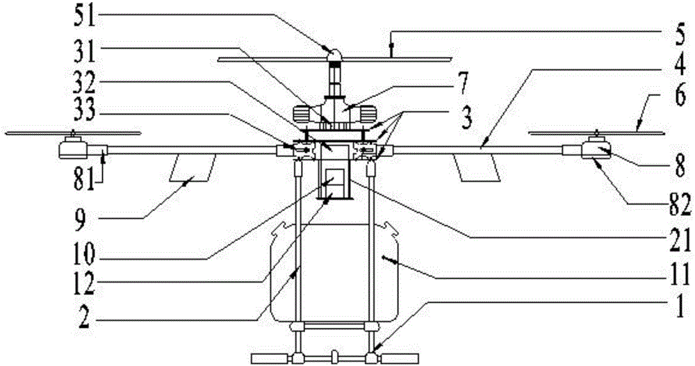
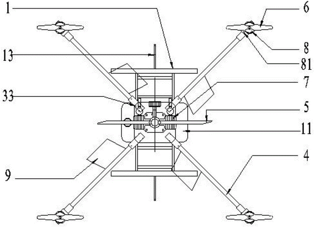
[0026] This embodiment provides a multi-rotor plant protection drone, such as figure 1 As shown, including landing gear 1, fuselage 2, frame 3, machine arm 4, main rotor 5, auxiliary rotor 6, spraying system and control system, fuselage 2 is arranged on the top of landing gear 1 and is connected with landing gear 1, Frame 3 is arranged on the top of fuselage 2 and is connected with fuselage 2, and machine arm 4 is installed on the frame 3, and machine arm 4 is an even number and symmetrically distributed on the frame 3, and the top of frame 3 is provided with engine 7, The main rotor 5 is connected with the output shaft of the engine 7, and each arm 4 is provided with a motor 8, and the output shaft of each motor 8 is connected with the corresponding auxiliary rotor 6, and each arm 4 is provided with a spoiler 9, Spoiler 9 is used to counteract the anti-torque effect that main rotor 6 rotates, and control system, engine 7 and motor 8 are all connected to power supply 10, and c...
Embodiment 2
[0029] This embodiment provides a multi-rotor plant protection drone, such as figure 1 , 2 As shown, on the basis of Embodiment 1, the control system of this embodiment includes an engine control system arranged on the frame 3, the engine control system is connected with a steering gear 31 in communication, and a rocker is arranged on the steering gear 31. The swing end of the rod is connected with one end of a connecting rod, and the other end of the connecting rod is connected with the throttle of the engine. The engine control system can control the working state of the rocker on the steering gear 31 according to the control signal. The steering gear 31 rotates the end connected to the rocker, drives the other end of the rocker to swing, and then drives the connecting rod to move through the swing of the rocker. Thereby controlling the closure of the throttle, controlling the intake air volume of the engine, thereby regulating the rotating speed of the main rotor 5 .
[0...
PUM
 Abstract
Description
Claims
Application Information