

Multi-rotor type aircraft
A multi-rotor aircraft and auxiliary rotor technology, applied in the field of aircraft, can solve the problems of limited load and flight time
- Summary
- Abstract
- Description
- Claims
- Application Information
AI Technical Summary
Problems solved by technology
Method used
Image

Examples
Embodiment 1
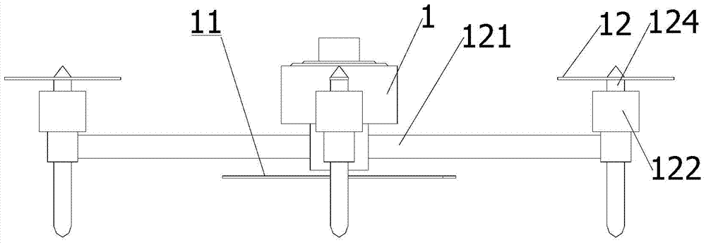
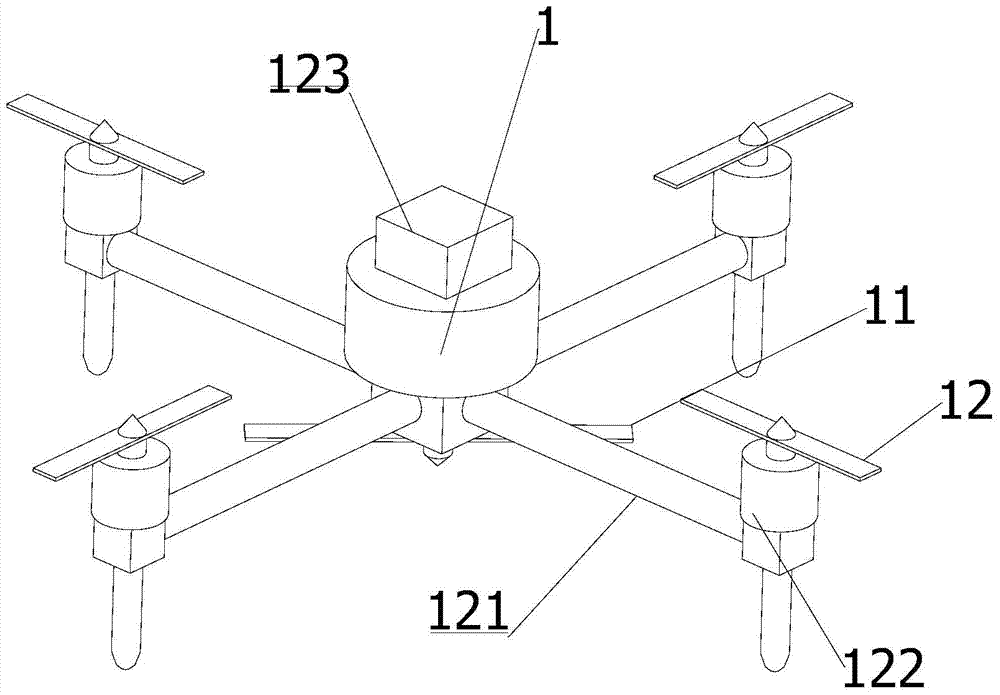
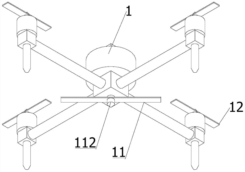
[0037] figure 1 The front view of the multi-rotor aircraft provided by the embodiment of the present invention; figure 2 A three-dimensional schematic diagram of a multi-rotor aircraft provided by an embodiment of the present invention; image 3 Another perspective view of the multi-rotor aircraft provided for the embodiment of the present invention; as Figure 1-3 As shown, the multi-rotor aircraft provided by the embodiment of the present invention includes a main rotor 11 and several auxiliary rotors 12, wherein the main rotor 11 is driven by a fuel engine (not shown in the figure), and the main rotor 11 is installed on the body 1 of the fuel engine. The lower or upper end of the center position. The secondary rotors 12 are arranged around the machine body 1 , and the secondary rotors 12 are respectively driven by electric motors 122 .
[0038] In the above scheme, the main rotor 11 is installed on the lower side of the center of the body 1 of the fuel engine, and the m...
Embodiment 2
[0044] Figure 4 A three-dimensional schematic diagram of a multi-rotor aircraft provided by another embodiment of the present invention; Figure 5 A three-dimensional schematic diagram of a multi-rotor aircraft provided for another embodiment of the present invention; as Figure 4 and Figure 5 As shown, the multi-rotor aircraft provided by another embodiment of the present invention includes a main rotor 11 and several auxiliary rotors 12, wherein the main rotor 11 is driven by a fuel engine (not shown in the figure), and the main rotor 11 is installed on the fuel engine. The lower end or upper end of the central position of the body 1. The secondary rotors 12 are arranged around the machine body 1 , and the secondary rotors 12 are respectively driven by electric motors 122 .
[0045] In this embodiment, the plane of the auxiliary rotor 12 has an included angle with the plane of the body 1 (see Figure 4 ). Specifically, the auxiliary rotor 12 in the opposite direction ...
Embodiment 3
[0050] This embodiment serves as a kind of alternative scheme of embodiment 2, see Image 6 with Figure 7 , according to needs, this multi-rotor aircraft also includes balance wing 13, and the number of balance wing 13 is 1 or 2, and it is also directly driven by electric motor, and in this embodiment, the plane where balance wing 13 is located is the same as the plane where main rotor 11 is located. The plane is vertical, so that the anti-torque moment of the main rotor 11 can be offset by the balance wing 13 to control the yaw attitude, and then the inclined installation angle of the auxiliary rotor 12 in the left and right directions can be canceled.
[0051] As a preferred embodiment, the multi-rotor aircraft includes 4 auxiliary rotors 12 and 1 balance wing 13, specifically, an extension arm 131 is extended on the arm of one of the auxiliary rotors 12, and at the end of the extension arm 131 Balance motor 132 is fixedly installed, and balance wing 13 is driven by balanc...
PUM
 Abstract
Description
Claims
Application Information