Power supply management system for solar energy unmanned aerial vehicle

A solar unmanned aerial vehicle and power supply management technology, applied in load supply circuits, current collectors, photovoltaic power generation, etc., can solve problems such as inability to change power supply methods, increase aircraft crashes, adjust flight strategies, etc., to reduce the possibility of accidental damage , the judgment condition is flexible, and the effect of improving the utilization rate

Pending Publication Date: 2017-03-22
CHINA JILIANG UNIV
View PDF7 Cites 16 Cited by
  • Summary
  • Abstract
  • Description
  • Claims
  • Application Information

AI Technical Summary

Problems solved by technology

[0004] Most of the existing power supply management systems for solar-powered drones are a single mode in which the solar energy charges the energy storage battery and then supplies power to the power system through the energy storage battery. The power loss generated through the intermediate link is relatively large, and the power supply cannot be flexibly changed according to the lighting conditions. way, not conducive to saving energy to achieve the purpose of long flight
[0005] Most of the existing systems are simple power supply management systems, which only distribute and manage the received solar energy, and cannot timely adjust flight strategies according to light and power conditions to save energy and ensure long-term flight
In the case of poor lighting conditions and insufficient power of the energy storage battery, it is easy to increase the risk of aircraft crash due to insufficient power

Method used


Image

  • Power supply management system for solar energy unmanned aerial vehicle
  • Power supply management system for solar energy unmanned aerial vehicle
  • Power supply management system for solar energy unmanned aerial vehicle

Examples


Embodiment Construction

[0041] The present invention will be further described below in conjunction with the accompanying drawings and embodiments.

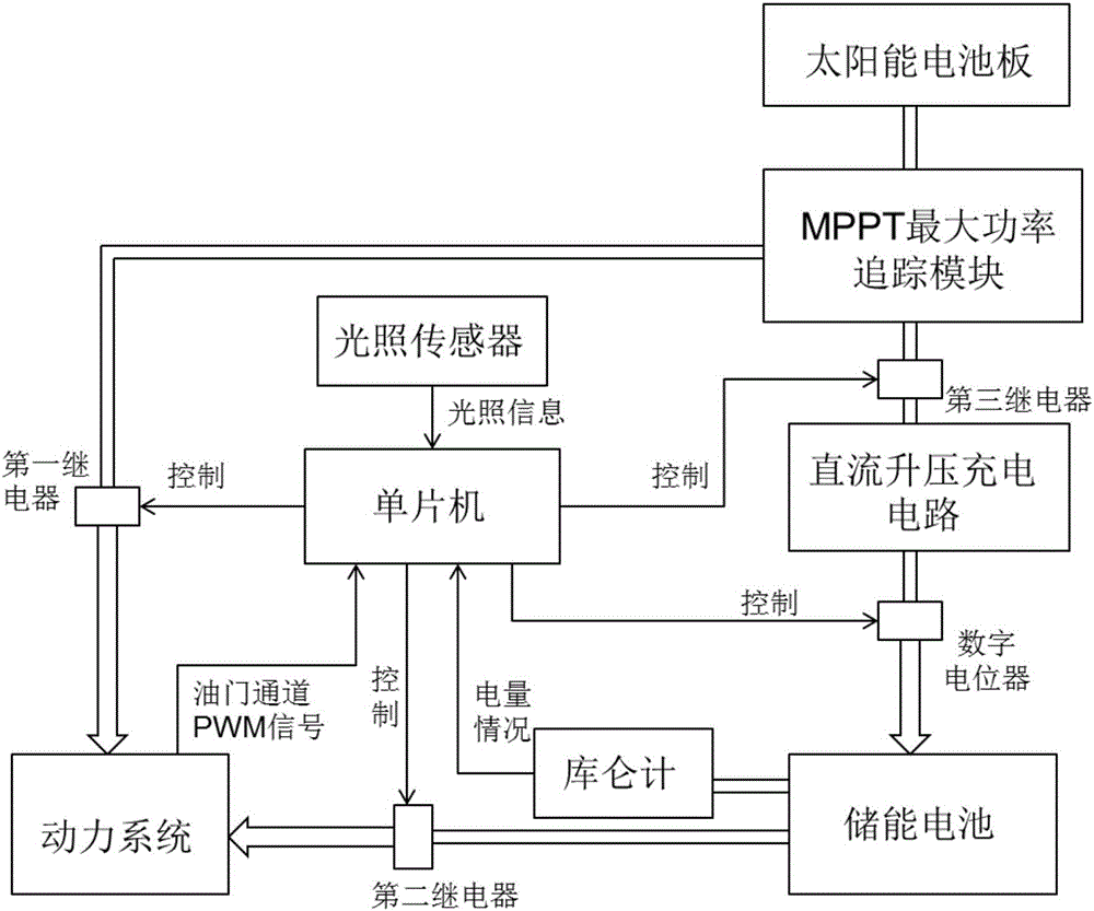
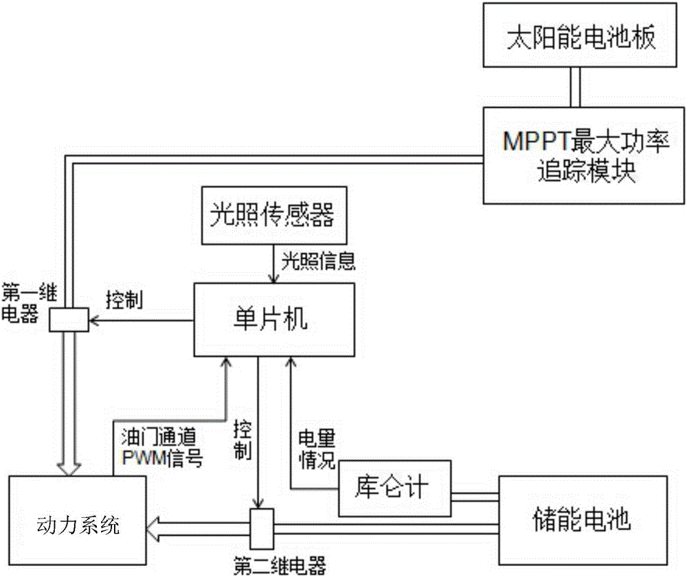
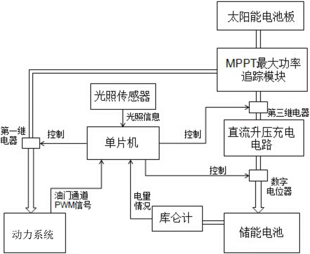
[0042] Such as figure 1 As shown, the present invention includes MPPT maximum power tracking module, light sensor, DC boost module (DC-DC module), coulomb counter, multiple relays and main control module, and light sensor is placed on the top surface of the solar unmanned aerial vehicle fuselage In the middle, the light sensor is connected to the main control module, the input end of the MPPT maximum power tracking module is connected to the solar panel, and one output end of the MPPT maximum power tracking module is connected to the power system of the solar drone after passing through the first relay. The other output terminal of the power tracking module is connected to the energy storage battery through the third relay and the DC boost module in turn, the energy storage battery is connected to the power system through the second relay, and the energ...


PUM


Abstract

The present invention discloses a power supply management system for a solar energy unmanned aerial vehicle. The system comprise a MPPT (Maximum Power Point Tracking) module, an illumination sensor, a direct current boosting module, a coulometer, a plurality of relays and a master control module. The illumination sensor is connected with the master control module, the MPPT module is connected with a solar panel, the MPPT module is connected with a power system and an energy storage battery, the energy storage battery is connected with a power motor through a second relay, and the energy storage battery is connected with the master control module through the coulometer. The mode of utilizing solar energy to preferentially supply power to the power system is employed, the residual electric energy is supplied to the energy storage battery, and if the power requirement is high, the two-way power supply mode is employed to add the electric energy provided by the power supply system. The power supply management system for the solar energy unmanned aerial vehicle is reasonable in structure and high in universality, can realize uninterruptible power supply, continuously charge the energy storage battery and perform switching selection of the power supply in different conditions so as to reduce the electric energy loss caused by various reasons.

Description

technical field [0001] The invention relates to a power supply management system, in particular to a power supply management system for a solar unmanned aerial vehicle in the field of unmanned aerial vehicle research. Background technique [0002] Solar-powered drones refer to unmanned aircraft powered by solar energy, which convert solar energy into electrical energy and store it in energy storage batteries through photovoltaic cells. The operation of the entire UAV system is maintained by releasing the electrical energy stored in the energy storage battery. [0003] High-altitude and long-endurance solar-powered drones have the advantages of high flight altitude, long working hours, wide coverage area, flexible use, low operating cost and no environmental pollution. It is one of the future development directions of drones. To ensure the uninterrupted flight of solar-powered UAVs for a long time, a reliable power supply management system is designed to reasonably allocate ...

Claims


Application Information

Patent Timeline
Patent Type & Authority Applications(China)
IPC IPC(8): H02J7/35H02J7/00
CPCH02J2007/0067H02J7/0063H02J7/007H02J7/35Y02E10/56
Inventor 陈清玄郑恩辉陈俊胤徐欣琦章浩陈冬梅吴钍荣
Owner CHINA JILIANG UNIV
Why Eureka
Try Eureka