Electrical machines with reduced cogging

a technology of electric machines and cogging, applied in the direction of dynamo-electric machines, magnetic circuit rotating parts, magnetic circuit shape/form/construction, etc., can solve the problems of reducing efficiency and reliability, unwanted vibration and noise, and electrical machine operation, so as to reduce the rated power of the machine. , the effect of being understood

Active Publication Date: 2010-05-11
GE POWER CONVERSION
View PDF10 Cites 3 Cited by
  • Summary
  • Abstract
  • Description
  • Claims
  • Application Information

AI Technical Summary

Benefits of technology

[0023]The presence of displaced magnet poles in machines according to this invention leads to a reduction in cogging due to its effect on the potential energy of the relative positions of the rotor relative to the stator. Specifically, displacing the magnet poles reduces the magnitude of the potential energy difference between the rotor's highest and lowest potential energy positions relative to the stator. This is because when the magnet poles are not uniformly spaced around the circumference of the rotor, when any one individual magnet pole is in its lowest possible potential energy position relative to the winding slots any other magnet pole that is displaced from its reference position relative to that individual magnet pole by an amount that is not an integral multiple of the winding slot pitch will be in a higher potential energy position relative to the winding slots. This means that the overall potential energy of the rotor in that position will be raised compared to the equivalent position of a rotor which has magnet poles uniformly spaced at integral multiples of the winding slot pitch. An equivalent argument applies to the high energy positions of the rotor. That is, the presence of displaced magnet poles lowers the energy of the high potential energy positions of the rotor relative to the stator.
[0058]An electrical machine according to this invention may also incorporate other features that reduce cogging. For example, the magnet poles may be skewed such that they are not parallel to the axis of the rotor or the magnet poles may be shaped to reduce cogging.

Problems solved by technology

A common problem encountered in the operation of electrical machines is cogging.
Cogging during the operation of electrical machines can result in decreased efficiency and reliability, as well as causing unwanted vibration and noise and, in extreme cases, complete failure.
The effect is also well known in induction machines in which the magnet poles and winding slots interact to cause serious cogging for particular numbers of winding slots.
However, in some cases this may not be preferred, or even possible.
For example, in large-scale electrical machines the options for having differing numbers of winding slots that are not multiples of the number of magnet poles are very limited as the non-synchronous flux patterns that result from such changes in the number of winding slots inevitably lead to additional losses in the magnet poles.
These losses may be extremely high and even render the method unusable.
An alternative method of reducing cogging is to incorporate magnetic wedges in the winding slots but this method is costly.
It is also possible to use ‘semi-closed’ winding slots to reduce cogging but for the types of winding that comprise formed coils and are common in large machines this type of winding slot can lead to an unacceptably high winding cost.
Typically, it is proposed that the outer surfaces of the magnet poles are formed such that the air gap between the stator and the magnet poles is not uniform.
However, in most cases this rotor construction will not be preferred to the conventional construction due to its impact on other design considerations.
For example, this construction results in complete asymmetry of the positioning of the magnet poles around the rotor.
If the electrical machine is intended for high-speed use this asymmetry is undesirable as it means the magnet pole arrangement is not mechanically balanced.
Depending upon the angular width of the magnets that form these magnet poles, this could lead to the two magnet poles being in contact with or impinging upon one another, which is generally undesirable, as discussed later.
Finally, the strict requirement for the positioning of the magnet poles also leads to a lack of flexibility in the design of machines according to U.S. Pat. No. 4,713,569.

Method used


Image

  • Electrical machines with reduced cogging
  • Electrical machines with reduced cogging
  • Electrical machines with reduced cogging

Examples


Embodiment Construction

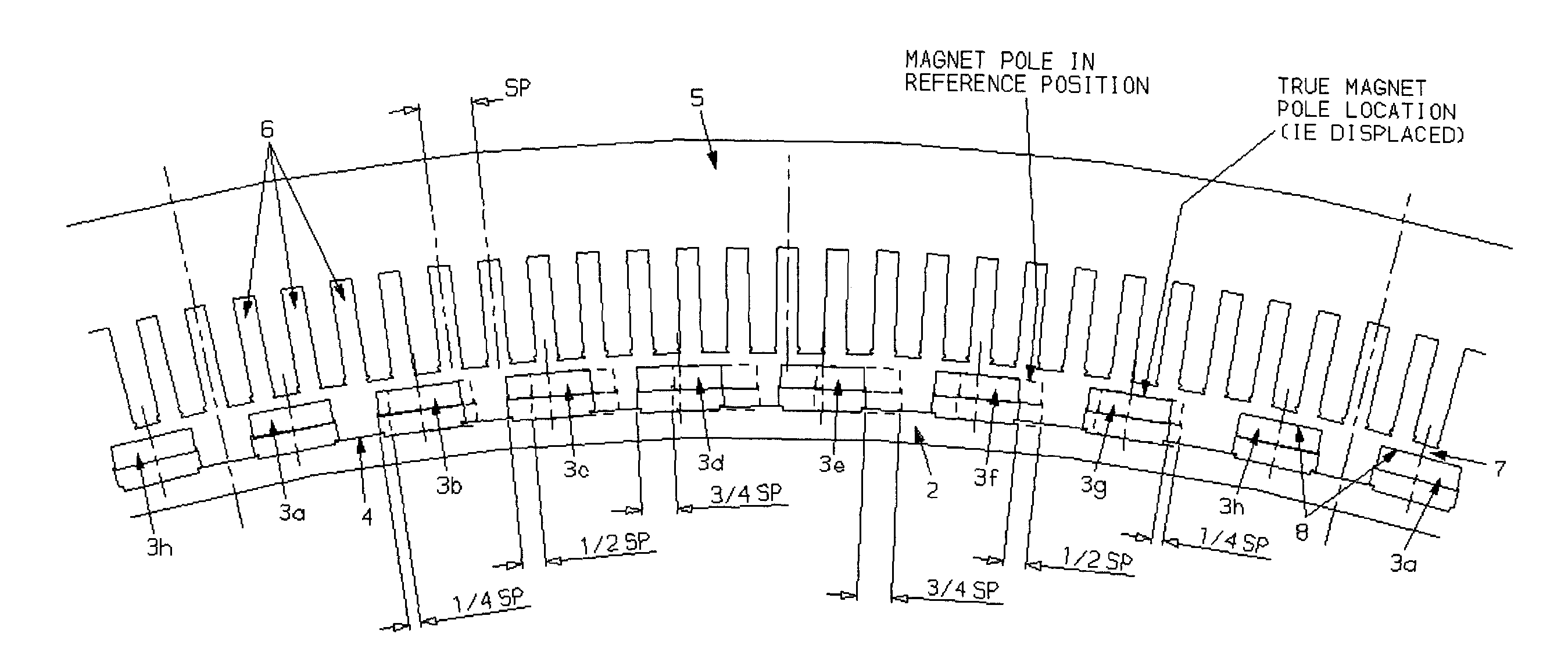
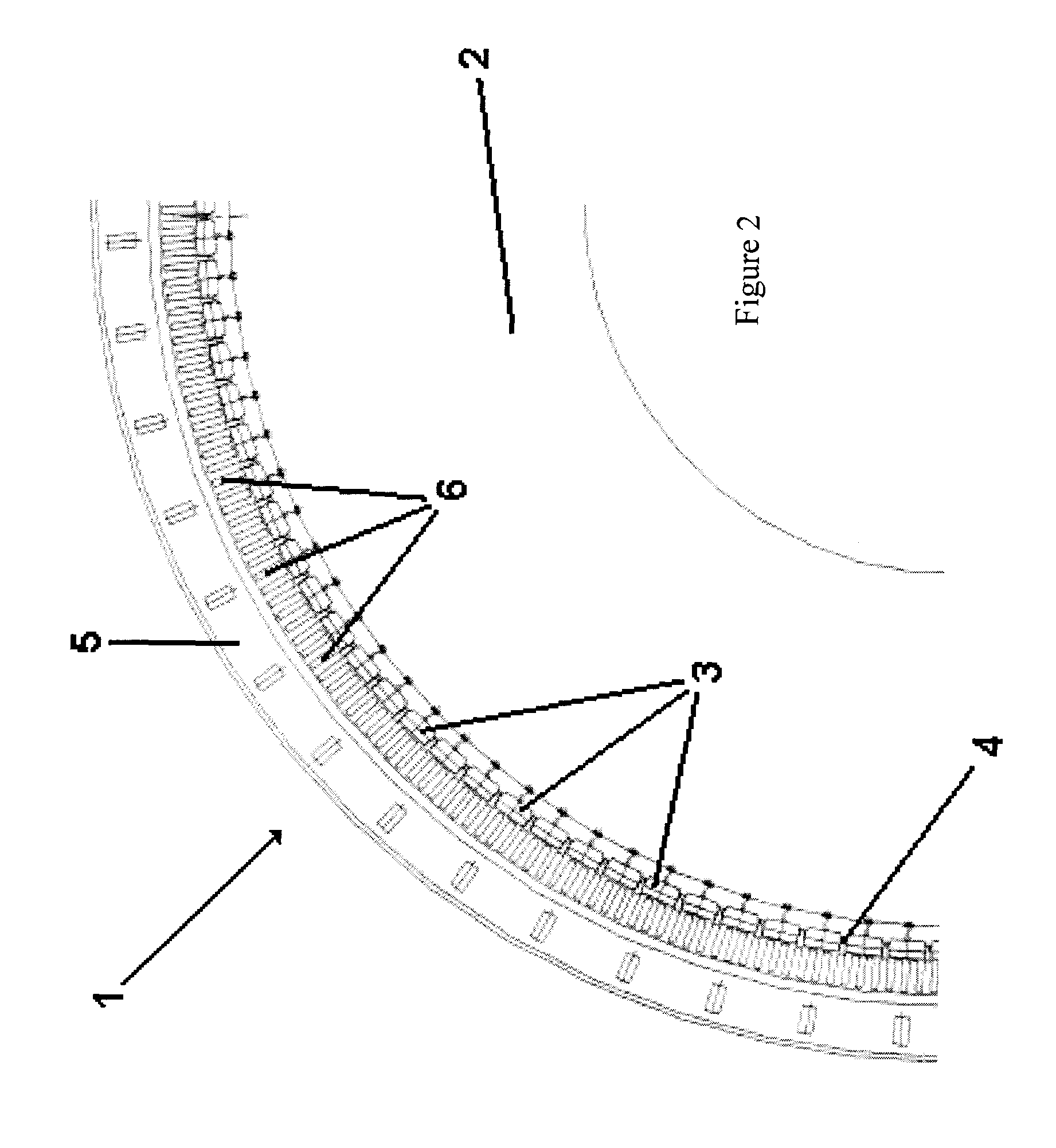
[0067]A typical conventional construction of a low-speed large-diameter electrical generator 1 is shown in FIGS. 2 and 3. The rotor 2 has one hundred and twelve magnet poles 3 mounted around its outer rim 4. The magnet poles 3 are equally spaced from each other such that they are equally spaced around the circumference of the rim 4. That is, the magnet poles 3 are each positioned in their reference positions and the reference angular magnet pole pitch is 3.21° (360° / 112). The rotor 2 is rotatably mounted within a stator 5 and there is an air gap 7 formed between the inner surface of the stator 5 and the outer surface 8 of the magnet poles 3. The stator 5 contains three hundred and thirty-six equally spaced winding slots 6 formed in its inner surface i.e. three winding slots per magnet pole. This equates to a reference angular winding slot pitch Sp of 1.07°, a third of the magnet pole pitch. Each winding slot 6 contains a portion of a stator winding (not shown) and the winding slots ...


PUM


Abstract

The present invention provides an electrical machine 1 with reduced cogging. The magnet poles 3 of the electrical machine are comprised of at least two separate groups of at least two circumferentially adjacent magnet poles. One of the circumferentially outer magnet poles 3 in one of the groups of magnet poles is defined as being in its reference position. The reference position of each other magnet pole 3 is defined as the position each other magnet pole would occupy if all the magnet poles were equally circumferentially spaced around the first or second body and the one circumferentially outer pole was in its reference position. At least one of the circumferentially outer magnet poles 3 in each group is sited in its reference position. At least one magnet pole 3 in each group is a displaced magnet pole and is sited in a position that is displaced from its reference position by an amount that is not equal to an integral multiple of the reference angular pitch of the winding slots. The displacement of the magnet poles 3 provides a pronounced reduction in cogging.

Description

FIELD OF THE INVENTION[0001]This invention relates to permanent-magnet based, alternating current, rotating electrical machines and the minimizing of cogging torque exhibited by such machines. In particular it relates to electrical machines with reduced cogging due to the displacement of their magnet poles.BACKGROUND OF THE INVENTION[0002]A common problem encountered in the operation of electrical machines is cogging. Cogging is the presence of non-linear magnetic torque during the operation of the machine due to the effect of the geometry of the rotor and the stator at the air gap on the flux distribution and the forces between the rotor and the stator. Specifically, it is caused by the rotor having preferred low potential energy positions relative to the stator, where the attraction between the rotor and stator is at a maximum, and corresponding high potential energy positions disposed between each of the low energy positions. It is the difference in potential energy between these...

Claims


Application Information

Patent Timeline
Patent Type & Authority Patents(United States)
IPC IPC(8): H02K1/27
CPCH02K1/278H02K29/03H02K21/14H02K1/2781H02K1/17H02K1/274H02K21/12H02K21/22
Inventor CLARK, PAUL EATON
Owner GE POWER CONVERSION
Why Eureka
Try Eureka