Sharpening device

a technology of sharpening device and blade, which is applied in the direction of edge grinding machine, other manufacturing equipment/tools, manufacturing tools, etc., can solve the problems of unsupported thin edge created by the intersection of the facets, inability to physically resist the force being applied, and relatively dull blade consequently, so as to reduce the size of the resulting burr at the edge of the blade, the effect of reducing the spring force and high effective

Active Publication Date: 2005-04-05
EDGECRAFT
View PDF13 Cites 98 Cited by
  • Summary
  • Abstract
  • Description
  • Claims
  • Application Information

AI Technical Summary

Benefits of technology

The geometry of the finishing apparatus can take many forms, however, this inventor has developed a novel, highly effective, low-cost combination of motor driven disks coated with ultra-fine diamonds where the abrasive coated disks are held by an exceedingly low-force spring action against a positioning stop on a motor driven shaft. The positioning stop serves to locate the surface of the abrasive coated disks immediately adjacent to knife guides positioned and angled ...

Problems solved by technology

The creation of the burr results from the fact that the very thin edge being created by the intersection of the facets is unsupported and too thin to physically resist the force being applied by the abrading process.
Old fashioned power driven sharpening stones that were rigidly mount...

Method used


Image

  • Sharpening device
  • Sharpening device
  • Sharpening device

Examples


Embodiment Construction

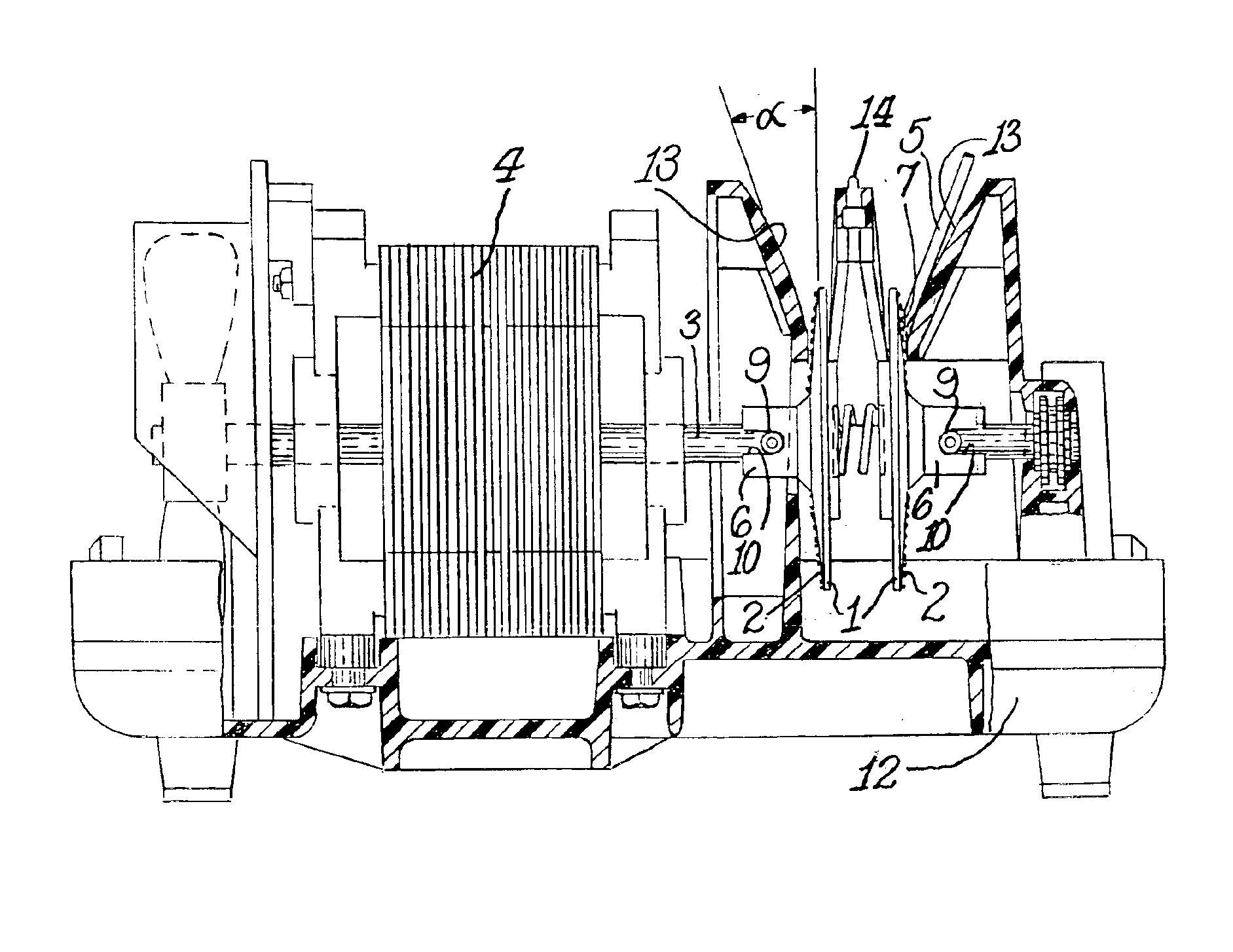
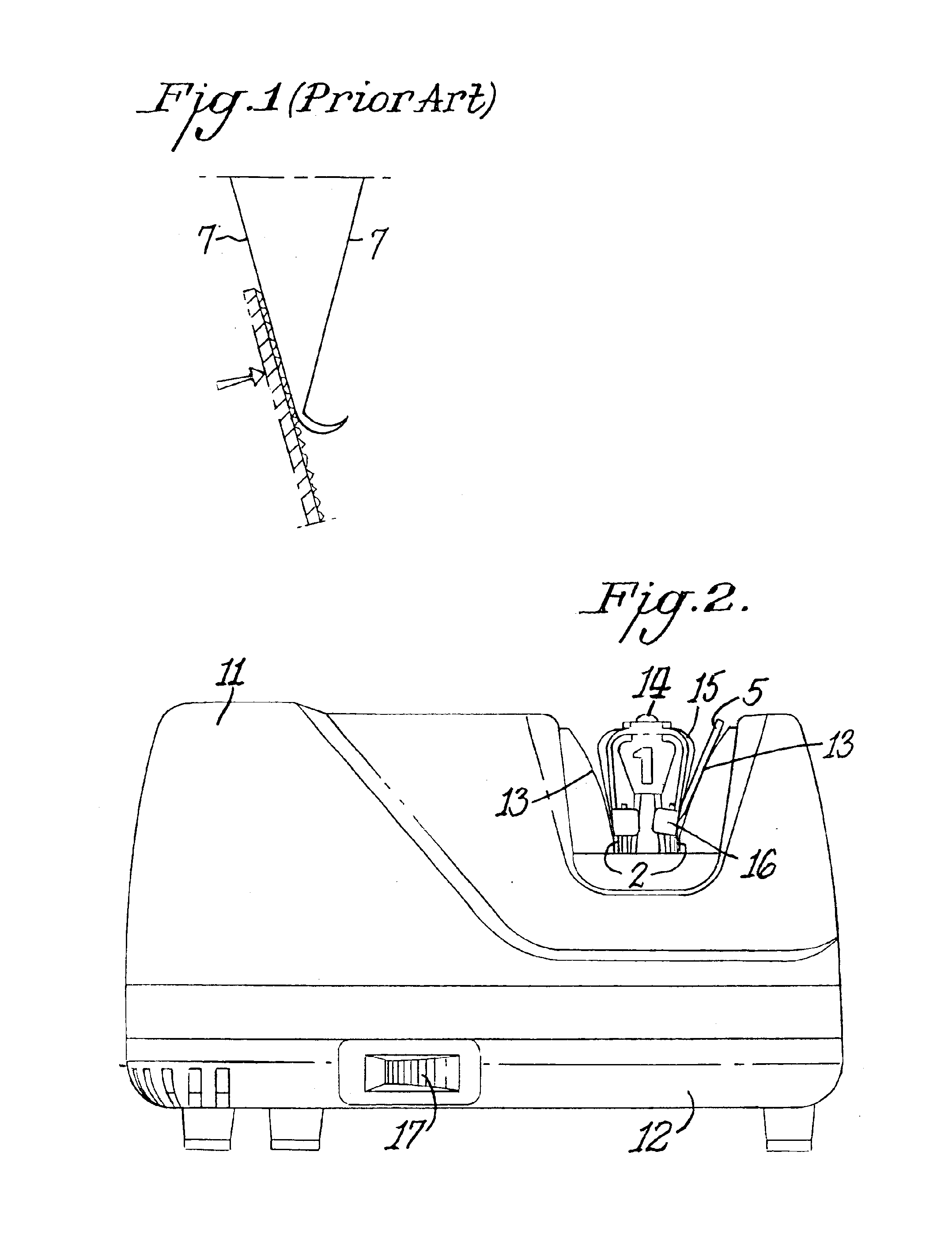
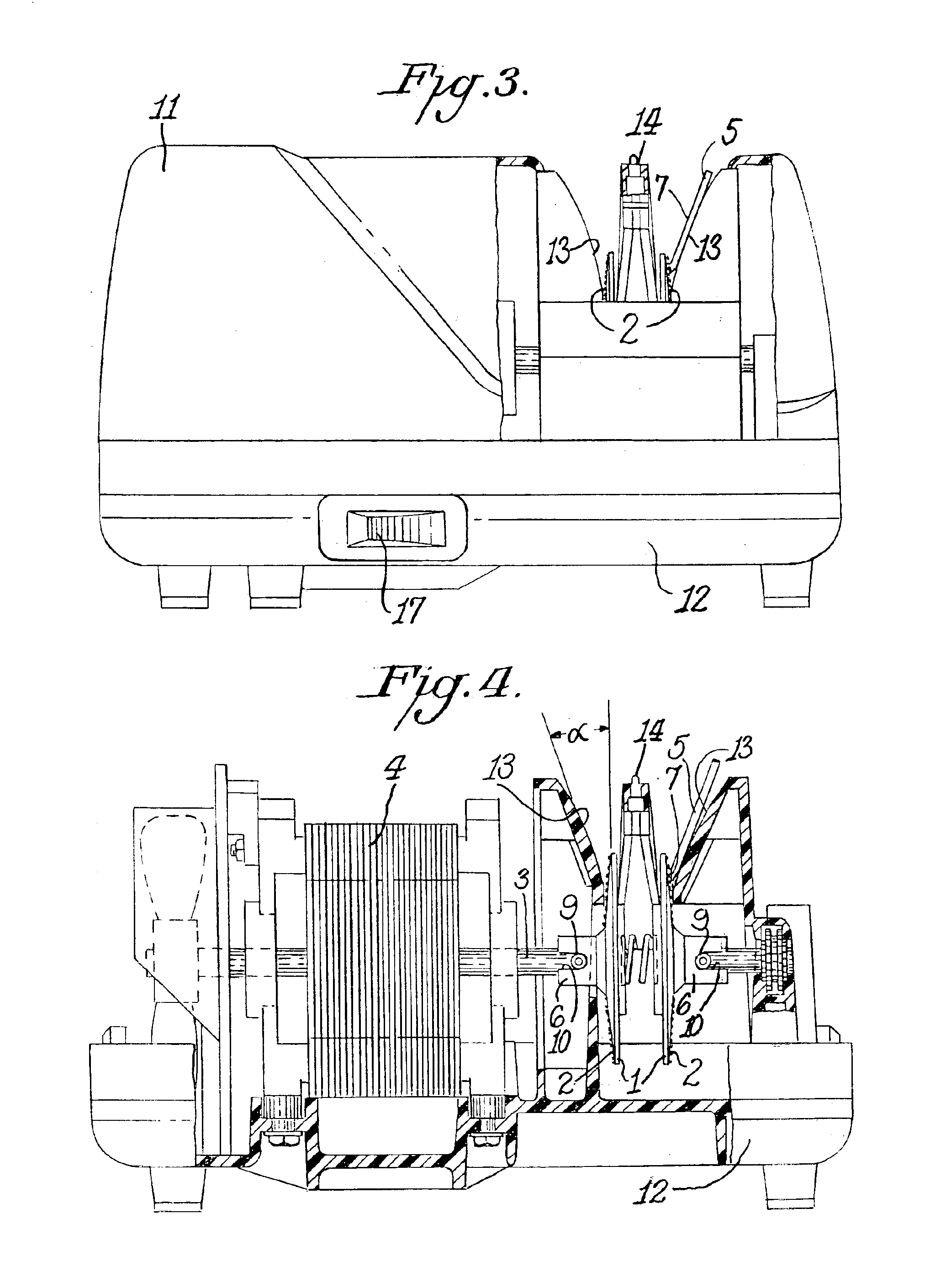
One physical arrangement for a sharpener that has proved effective for sharpening with ultra fine abrasives is shown by way of example in FIG. 4 in cut-away form. Two sharpening disks 1 with abrasive coated surfaces 2 are mounted on shaft 3 driven by an electrical motor 4. The disks 1 made of a metal stamping formed to present a uniform surface of rotation to the edge facet 7 of a knife 5 being shaped by contact with the abrasive surface 2 are mounted on hubs 6 which are driven by shaft 3. The hubs 6 each have a central cylindrical bore hole that is sufficiently larger than the diameter of the shaft 3 to allow the mounted disk 1 to be physically displaced when the knife edge facet 7 contacts the abrasive surface 2 of the disk. A compression spring 8 mounted between the disks 1 forces the disks to return to a rest position that is precisely established by drive pins 9 that are secured to rotate with shaft 3 and of a diameter that fits with clearance in the slot 10 of hubs 6. The term...


PUM

PropertyMeasurementUnit
Massaaaaaaaaaa
Diameteraaaaaaaaaa
Diameteraaaaaaaaaa

Abstract

A sharpener includes a motor driven shaft with at least one slidably mounted sharpening assembly consisting of a supporting hub structure mounted by its central bore hole on the shaft. The hub structure supports a symmetrically shaped rotating surface containing an ultra fine abrasive material. The rotating surface is pressed with a force of less than 0.2 lb. by a spring action to make sustained rotating abrading contact with a facet of a knife positioned by a knife guide to align the facet into contact with the surface containing the abrasive materials.

Description

FIELD OF INVENTIONThis invention relates to an improved power driven sharpening apparatus for knife edges and edges of metal cutting tools.BACKGROUND OF INVENTIONThere have been a wide range of devices and mechanisms for sharpening the edge of knives and cutting tools both manual and power driven. A number of these have been the subject of patents by this inventor including U.S. Pat. Nos. 4,627,194, 4,716,689, 4,807,399, 4,897,965, 6,113,476, and 6,012,971. These describe sharpeners capable of creating very sharp edges. The perfection and effectiveness of the final edge is in each case limited by the design of the final sharpening stage.SUMMARY OF INVENTIONThe invention relates to an improved design of a powered finishing stage that creates an exceedingly sharp and effective edge by minimizing the size of the burr resulting from the abrading actions during the metal removal process. The invention involves novel means that make it possible to use effectively abrasives of exceedingly ...

Claims


Application Information

Patent Timeline
IPC IPC(8): B24B3/36B24B3/00B24B3/54
CPCB24B3/546B24B3/36
Inventor FRIEL, SR., DANIEL D.FRIEL, JR., DANIEL D.HALL, SR., TERRY J.
Owner EDGECRAFT
Why Eureka
Try Eureka