Multiple-phase DC-DC converter topology

a converter and multi-phase technology, applied in the direction of electric variable regulation, process and machine control, instruments, etc., can solve the problems of low switching frequency, slow response, and high speed processors to power supplies, and achieve the effect of improving the converter's response to changes

Active Publication Date: 2005-09-13
ANALOG DEVICES INC
View PDF8 Cites 94 Cited by
  • Summary
  • Abstract
  • Description
  • Claims
  • Application Information

AI Technical Summary

Benefits of technology

[0015]A multiple-phase DC—DC converter topology is presented which overcomes the problems noted above. The invention adds at least one additional phase to an N-phase DC—DC converter to improve the converter's response to changes in load.

Problems solved by technology

The load a high speed processor presents to a power supply can go from low to high or vice versa in a very short time, particularly when running demanding software programs.
But a regulator having low switching frequencies and ripple currents typically requires the use of large output inductors, and tends to respond slowly to load changes.
Transient response is improved with the use of a higher output filter capacitance, but this adds cost and requires space.
However, to deliver high currents, expensive high switching speed components must be used to keep efficiency high, or more phases must be used to lower the current per phase and improve the power losses—again adding cost.
However, the “turn-off” output current slew rate, applicable when there is a sharp decrease in load current, is limited to Soff.
This results in a large error between Iout and Iload, with the error reduced at the Soff-limited rate.
This large overshoot is not acceptable for most designs.

Method used


Image

  • Multiple-phase DC-DC converter topology
  • Multiple-phase DC-DC converter topology
  • Multiple-phase DC-DC converter topology

Examples


Embodiment Construction

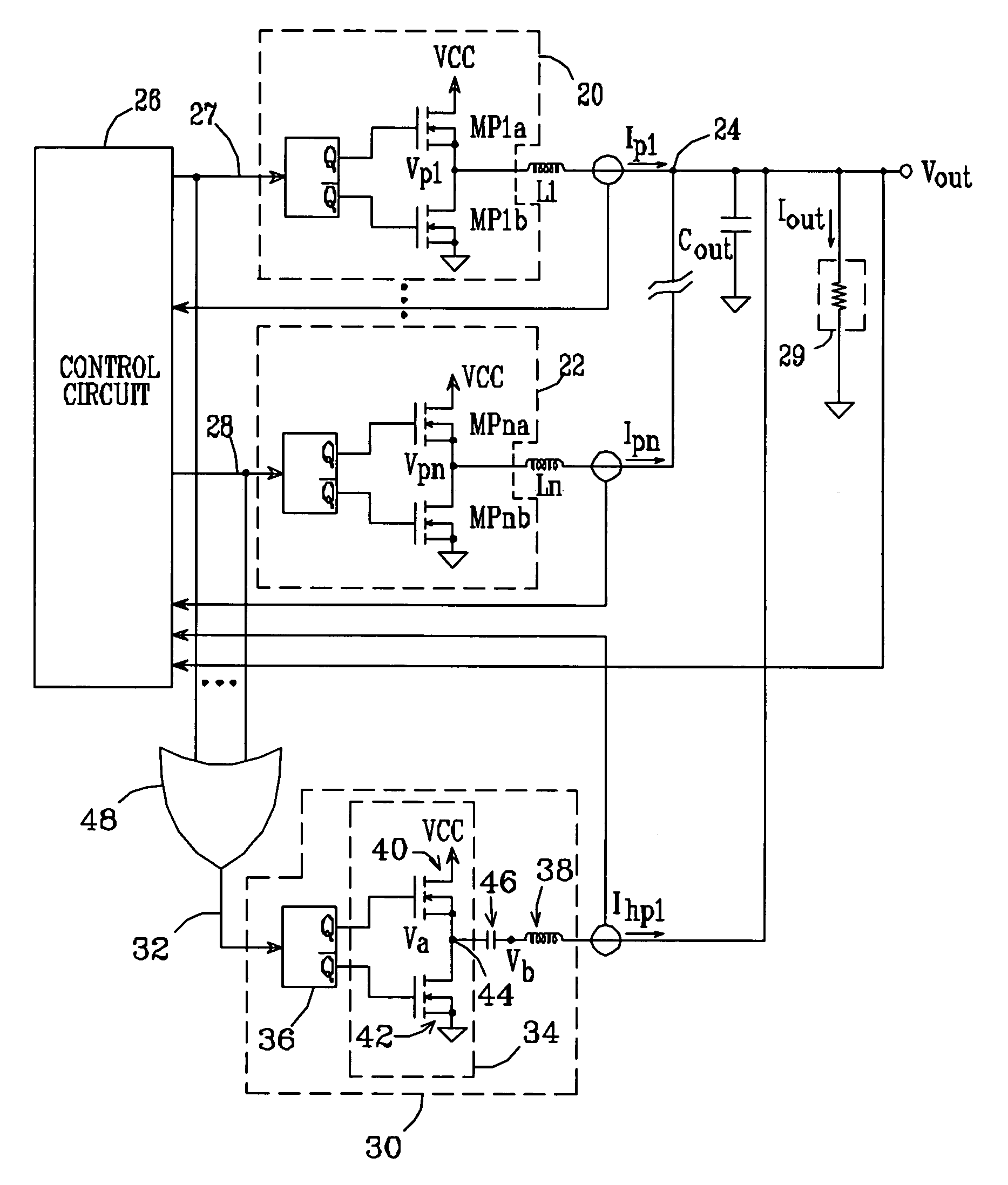
[0030]A schematic / block diagram illustrating the principles of a multiple-phase DC—DC converter in accordance with the present invention is shown in FIG. 2. The number of main phases is identified herein as “N”. For each phase, the regulator includes a switching circuit (20, 22) made up of one or more switching transistors (MP1a / MP1b, . . . , MPna / MPnb), with each switching circuit connected to one side of a respective output inductor (L1, . . . , Ln). The opposite, “output” sides of the inductors are connected together at a common output terminal 24. The N switching circuits are operated by a control circuit 26, which provides respective control signals 27, 28 to the switching circuits so as to generate respective phase currents Ip1, . . . , Ipn. The N phase currents are summed together at terminal 24 and thereby provide an output voltage Vout and a total output current Iout, suitable for driving a load 29. The converter normally includes a filter capacitor Cout to reduce the rippl...


PUM


Abstract

A multiple-phase DC—DC converter adds at least one additional phase to an N-phase DC—DC converter to improve the converter's response to changes in load. In one embodiment, an additional phase operates at a switching frequency greater than that of the N phases, to generate a current which is added to the N phase currents to improve the converter's response to changes in load. In another embodiment, an additional phase is configured to improve the converter's response to a load release. Here, the additional phase is kept off during load increase and steady-state conditions. However, when a load release occurs, the additional phase is turned on and acts to extract current from the converter's output terminal while the N phase currents slowly fall, to reduce the magnitude of output voltage overshoot that occurs on load release.

Description

REFERENCE TO EARLIER APPLICATION[0001]This application claims the benefit of provisional patent application No. 60 / 419,330 to T. Schiff, filed Oct. 17, 2002.BACKGROUND OF THE INVENTION[0002]1. Field of the Invention[0003]This invention relates to the field of switching voltage regulators, and particularly to multiple-phase DC—DC converters.[0004]2. Description of the Related Art[0005]Advanced microprocessors typically require power supplies that provide a low voltage (e.g., <2 volts) at high current. The trend is for these supply voltages to continue to fall, while the current demand increases.[0006]The load a high speed processor presents to a power supply can go from low to high or vice versa in a very short time, particularly when running demanding software programs. One way in which high currents are provided is with a multiple-phase switching regulator, in which the components of a number (N) of single-phase regulators are repeated to produce N output currents, which are sum...

Claims


Application Information

Patent Timeline
Patent Type & Authority Patents(United States)
IPC IPC(8): G05F1/10
CPCH02M3/1584H02M2003/1586H02M3/1586
Inventor SCHIFF, TOD F.
Owner ANALOG DEVICES INC
Why Eureka
Try Eureka