Brace-locking device for an aircraft undercarriage

a technology for aircraft undercarriage and brake lock, which is applied in the direction of undercarriage, transportation and packaging, and alighting gear. it can solve the problems of increasing the life of the spring and reducing the force acting on the spring

a technology for aircraft undercarriage and brake lock, which is applied in the direction of undercarriage, transportation and packaging, and alighting gear. it can solve the problems of increasing the life of the spring and reducing the force acting on the spring

US7967245B2Inactive Publication Date: 2011-06-28SAFRAN LANDING SYSTEMS

Image

  • Brace-locking device for an aircraft undercarriage
  • Brace-locking device for an aircraft undercarriage
  • Brace-locking device for an aircraft undercarriage

Examples


Embodiment Construction

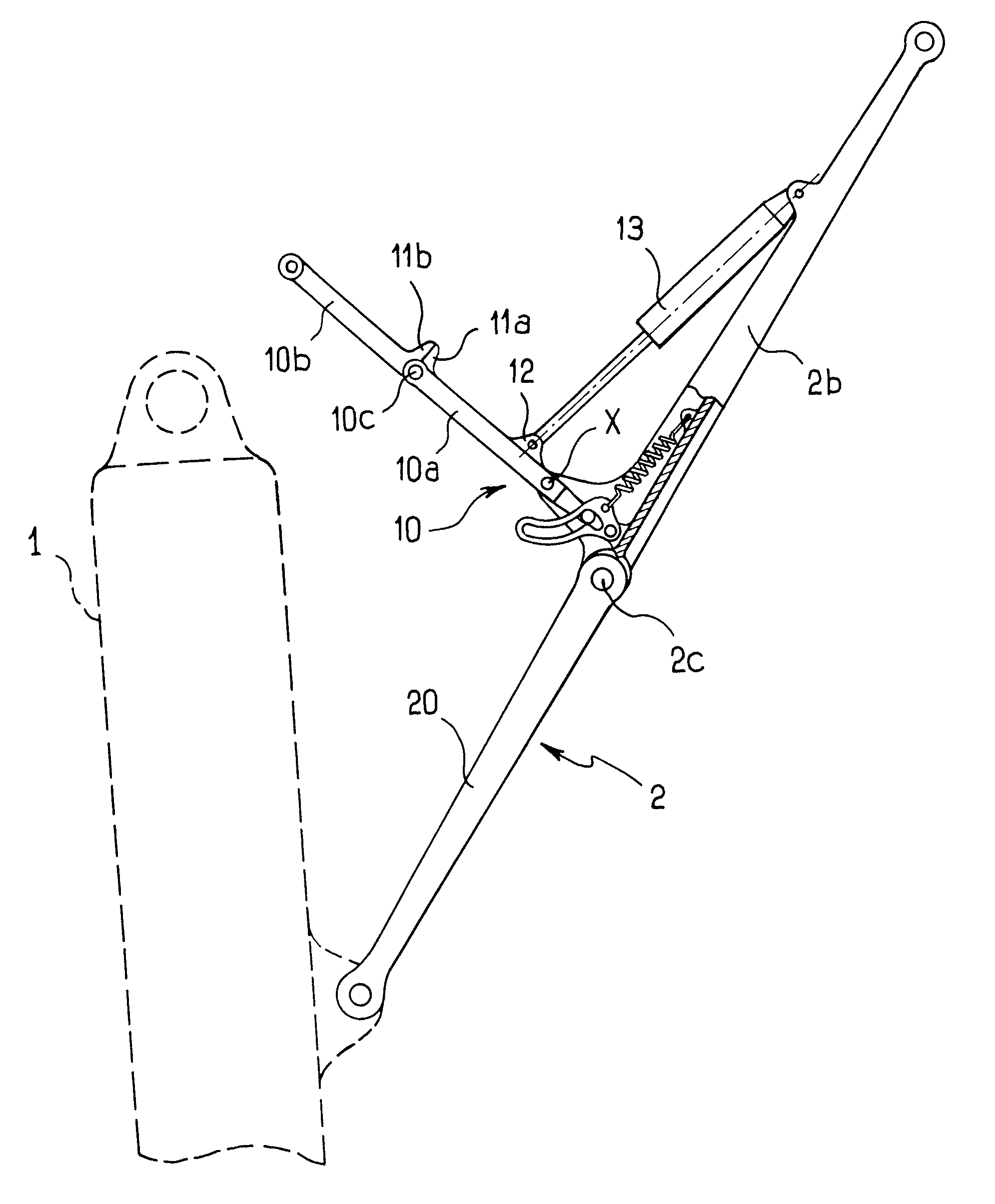
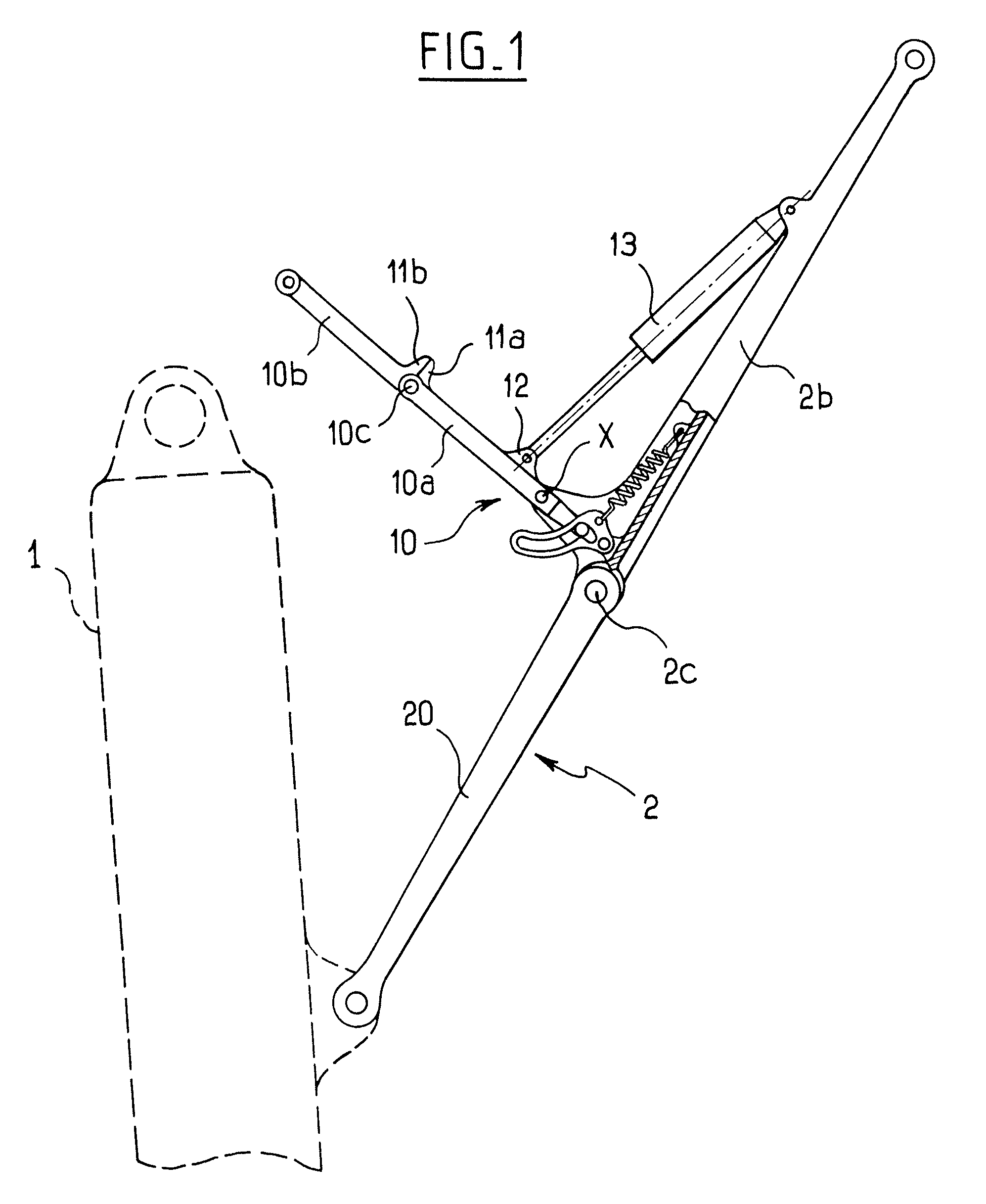
[0020]With reference to FIG. 1, the wind-brace device shown is for stabilizing an aircraft undercarriage 1 in the deployed position. The device comprises a brace 2 made up of a bottom link 2a hinged to the undercarriage 1, and a top link 2b hinged to the structure of the aircraft. The links 2a and 2b are hinged to each other via a central hinge or knee 2c.

[0021]A stabilizer member 10 serves to hold the links 2a, 2b substantially in alignment such that the undercarriage is stabilized in the deployed position. Below, this substantially aligned position is referred to as the “aligned position”, or as the “stabilization position” for the undercarriage in the deployed position.

[0022]The stabilizer member has a bottom arm 10a hinged to the top link 2b of the brace about a hinge axis X, and a top arm 10b hinged to the structure of the aircraft. The arms are hinged to each other by a central hinge 10c. The arms 10a, 10b are provided with abutments 11a, 11b that co-operate to define an arm-...


PUM


Abstract

The invention relates to a wind-brace device for an aircraft undercarriage, the device comprising a hinged brace movable between a folded position and a stabilization position for stabilizing the undercarriage in the deployed position, a stabilizer member for stabilizing the brace comprising two hinged-together arms, one of the arms having one end hinged to the brace about a hinge axis, and a spring member for urging the arm of the stabilizer member towards the locked position. The spring member is connected to a lever hinged to the brace, the lever presenting a slot in which there is engaged a finger secured to the arm that is hinged to the brace.

Description

CROSS-REFERENCE TO RELATED APPLICATION[0001]This application is entitled to the benefit of and incorporates by reference essential subject matter disclosed in French Patent Application No. 07 03175 filed on May 3, 2007.FIELD OF THE INVENTION[0002]The invention relates to a brace-locking device for an aircraft undercarriage.BACKGROUND OF THE INVENTION[0003]In general, undercarriages are hinged to the aircraft to move between a deployed position and a retracted position. To stabilize an undercarriage in the deployed position, it is known to make use of a wind-brace member or brace.[0004]In this respect, so-called “breakable” braces are known that comprise two links that are hinged together by means of a central hinge or knee, one of the links having one end hinged to the undercarriage while the other link has one end hinged to the structure of the aircraft. A stabilizer member keeps the two links in alignment when the undercarriage is in the deployed position, thereby stabilizing the ...

Claims


Application Information

Patent Timeline
28 Jun 2011
Publication
US7967245B2
IPC
B64C25/26; B64C25/18
CPC
B64C25/26
Inventors
SEROR-GOGUET, CHRISTELLE; MARTINEZ, LAURENT