
Child safety seat with load limited base

a child safety seat and load limitation technology, applied in the field of seats, can solve the problems of deliberately sacrificing the load limit feature, subjecting child safety seats to substantial acceleration, etc., and achieve the effect of reducing acceleration and thus the load on the seating elemen

Active Publication Date: 2011-06-28
BRITAX CHILD SAFETY
View PDF5 Cites 9 Cited by
  • Summary
  • Abstract
  • Description
  • Claims
  • Application Information

AI Technical Summary

Benefits of technology

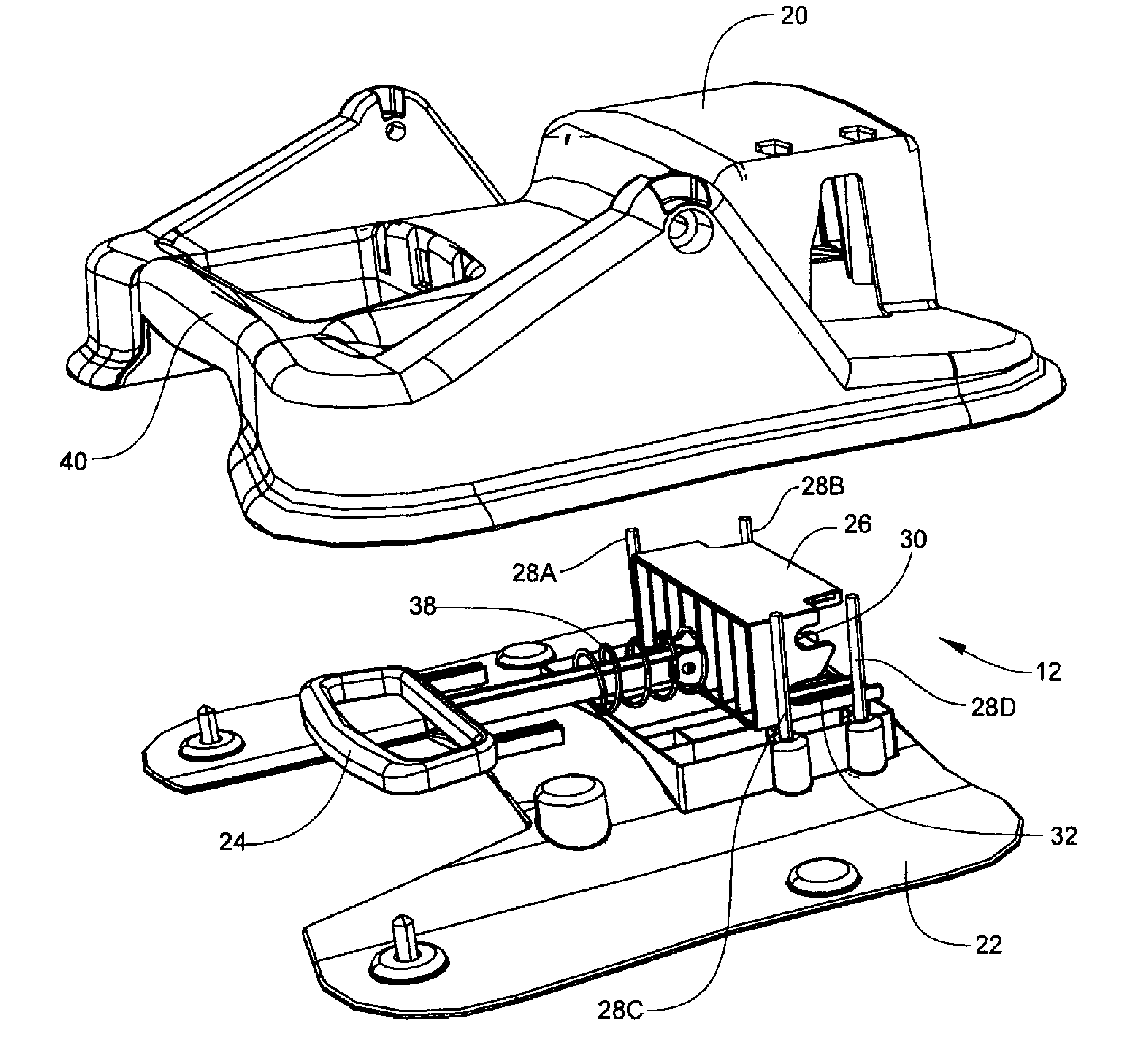
The invention is a child safety seat with a load-limited base. This means that the seat has a feature that reduces the acceleration of the seating element in a collision. This feature is achieved by using a load absorbing assembly that includes an elongated deforming member and a positioning block. The deforming member is selectively positioned in the positioning block to position the seating element in either a recline or upright position. In either position, the deforming member deforms at a controlled rate when the seat is subjected to a load of predetermined severity, reducing the acceleration and thus the load on the seating element. This feature makes the seat safer and more comfortable for the child, and also makes it easier for the seat to be replaced if it is damaged in a collision.

Problems solved by technology

Whether forward or rearward-facing, child safety seats are subject to substantial acceleration during a vehicle collision.
Because the sole purpose of the child safety seat is to protect the occupant, the load limiting feature can be made deliberately sacrificial whereby elements of the seat are damaged to the point where the seat is no longer operable.

Method used


Image

  • Child safety seat with load limited base
  • Child safety seat with load limited base
  • Child safety seat with load limited base

Examples


Embodiment Construction

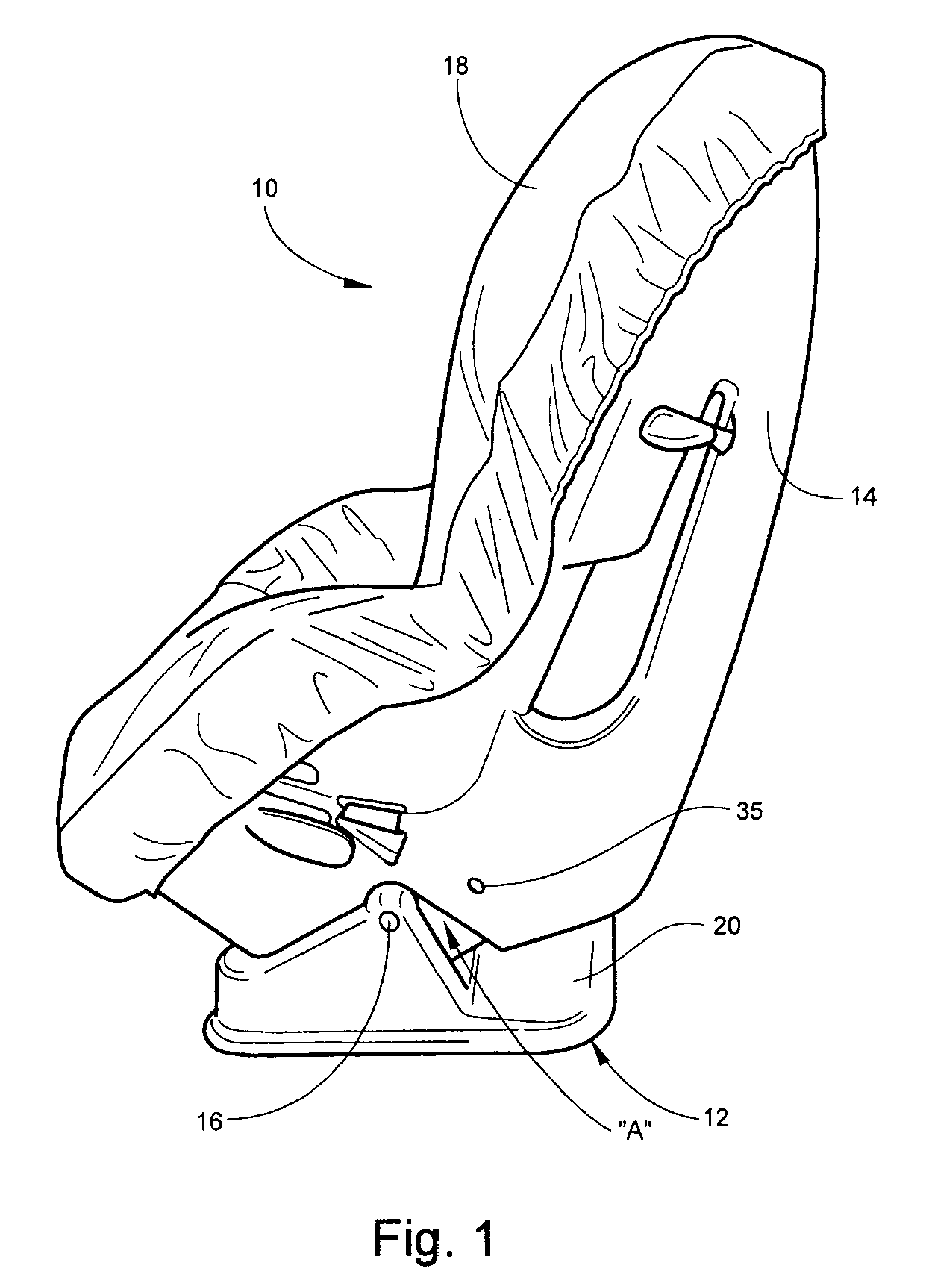
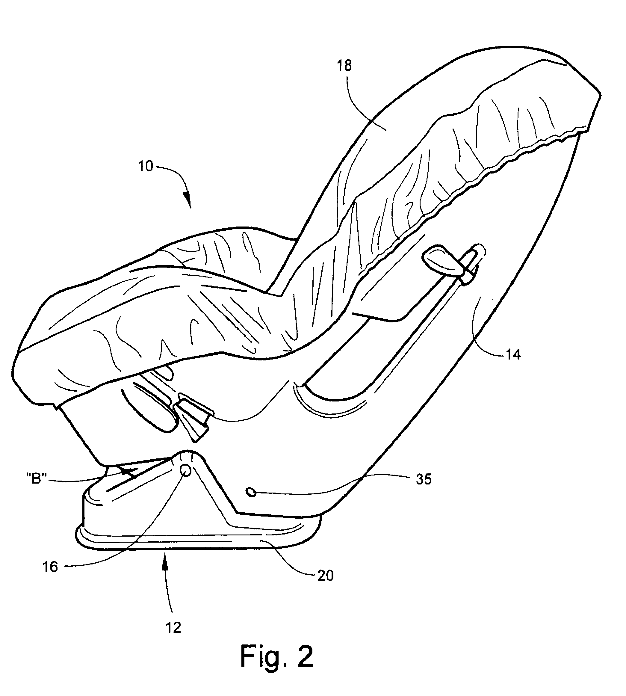
[0022]Referring now specifically to the drawings, a child safety seat according to the present invention is shown generally in FIGS. 1, 2 and 3 at reference numeral 10. The child safety seat 10 includes a seat base 12 and a seating element 14 that is mounted to the base by a axle 16 that extends transversely through the lower portion of the seating element and is mounted in an upper portion of the base, as shown. FIGS. 1 and 2 show the child safety seat 10 with the seating element 14 in its upright position and reclined position, respectively. The seating element 14 is covered by suitable padding and upholstery 18. FIG. 3 illustrates the load bearing areas of the seating element 14 on the base 12 in both the upright and reclined positions. FIG. 4 shows the structure of the seating element 14 underlying the upholstery 18. Seats 10 of the type described in this application are designed to accommodate children whose weight lies within differing ranges. The particular seat 10 described ...


PUM


Abstract

A load-limited seat base for a child safety seat, including an attachment element carried by the seat base for attaching the seat base to a seating element, and a transversely-extending load absorbing assembly positioned in the base and cooperating with the seating element to permit the seating element to be selectively positioned in a recline position and an upright position relative to the base. The load absorbing assembly includes an elongate deforming member and a positioning block having at least a first recline position and a second upright position corresponding to the recline position and the upright position within which the deforming member is positioned. The deforming member is selectively positionable in the positioning block to position the seating element in the selected recline or upright position. The deforming member in either the recline or upright position is positioned such that an acceleration of the base causing a load of predetermined severity deforms the deforming member against the positioning block at a controlled rate, reducing the acceleration and thus the load on the seating element.

Description

TECHNICAL FIELD AND BACKGROUND OF THE INVENTION[0001]This invention relates generally to seats, and specifically to child safety seats of the type that are releasably mounted onto car seats in order that the occupant be provided with enhanced security from injury during automobile travel. Such seats are now legally mandated in many parts of the world. The particular embodiment disclosed in this application is a convertible-type child safety seat designed to be placed in either a forward-facing or rearward-facing orientation with respect to the automobile or other vehicle in which it is mounted. In either case, the seat is attached to the vehicle seat with either the vehicle passenger seat belt, or with special latches, for example “Isofix” latches, by which the child safety seat is latched to the vehicle body.[0002]Whether forward or rearward-facing, child safety seats are subject to substantial acceleration during a vehicle collision. Various factors, including whether the collisio...

Claims


Application Information

Patent Timeline
Patent Type & Authority Patents(United States)
IPC IPC(8): B60R21/00B60N2/42
CPCB60N2/2821B60N2/2884B60N2/2875
Inventor PRZYBYLO, PHILLIPBUSTLE, BENJAMIN SHANE
Owner BRITAX CHILD SAFETY
Learn More