Captured screw assembly

Inactive Publication Date: 2011-06-28
COOPE ROBERT L +1
View PDF11 Cites 7 Cited by
  • Summary
  • Abstract
  • Description
  • Claims
  • Application Information

AI Technical Summary

Benefits of technology

[0008]Another object of the invention is to provide a new and improve

Problems solved by technology

This involves a significant amount of time, particularly if the required hardware is misplaced or lost.
This limits the space available for positioning the work piece on the

Method used


Image

  • Captured screw assembly
  • Captured screw assembly
  • Captured screw assembly

Examples


Embodiment Construction

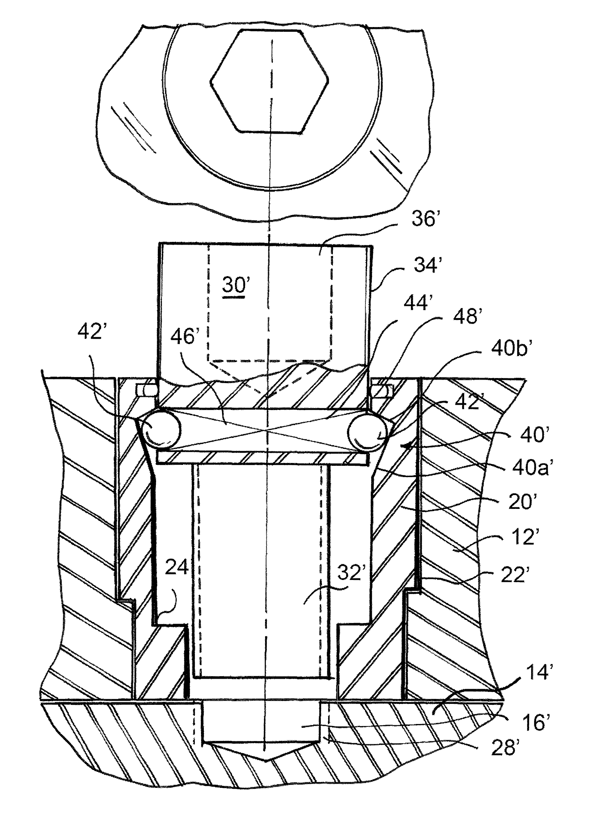
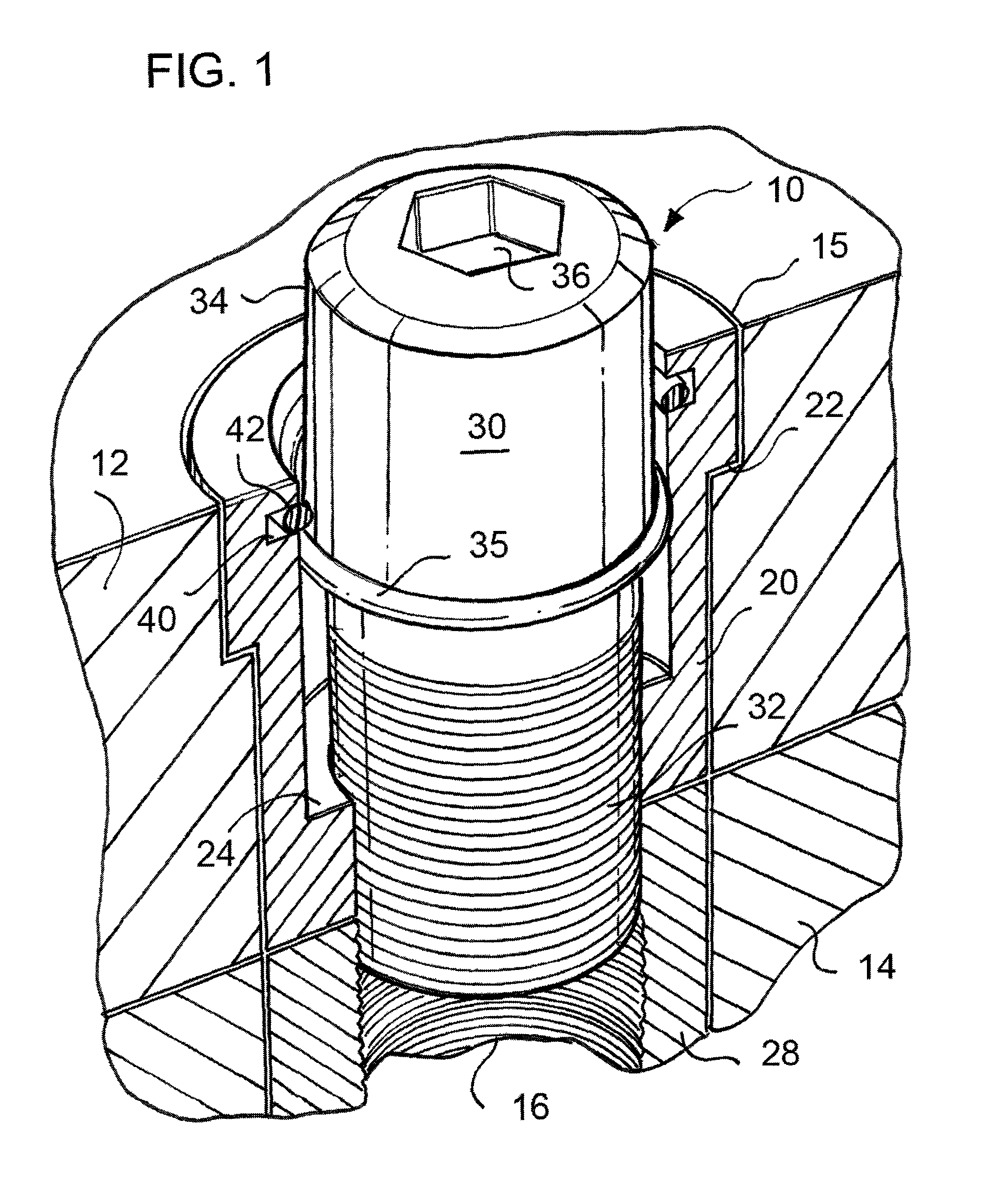
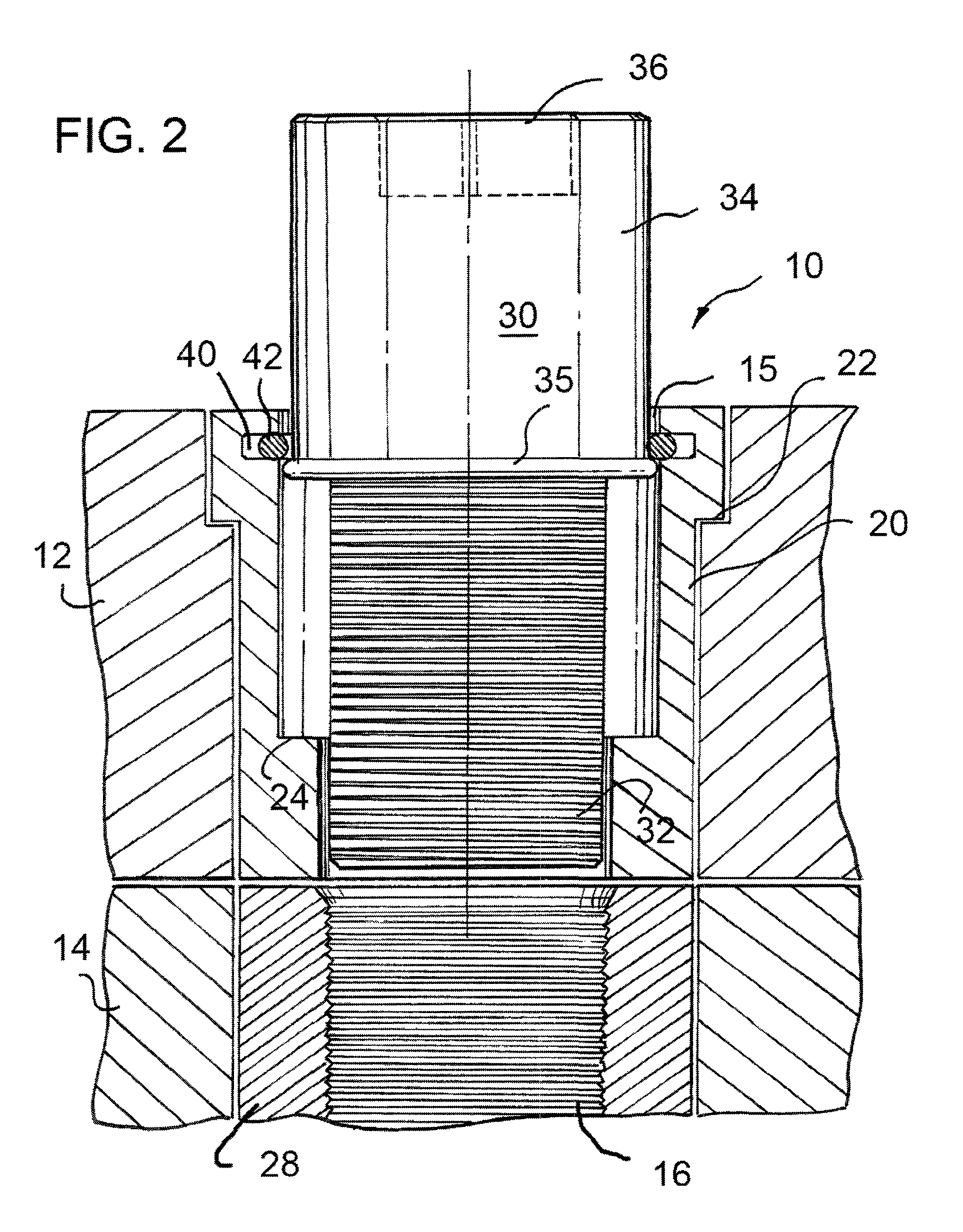
[0017]Turning now to FIGS. 1 and 2, which illustrate a captured screw assembly, generally designated 10, temporarily affixing a fixture plate 12 on a base plate 14. It will be understood by those skilled in the art that fixture plate 12 and base plate 14 have at least two locating holes therethrough for receiving locator dowel assemblies such as those disclosed in a copending application entitled Locator Dowel Assembly, filed of even date herewith, and incorporated herein by reference. Also, fixture plate 12 and base plate 14 have a plurality of captured screw assembly holes formed therein, only one of which is illustrated and will be discussed herein for convenience of understanding.

[0018]Fixture plate 12 has a hole 15 extending therethrough and base plate 14 has a hole 16 extending therethrough and axially aligned with hole 15 by at least two locator dowel assemblies (not shown). Hole 15 through fixture plate 12 is counterbored to receive the head of captured screw assembly 10, as...


PUM


Abstract

A captured screw assembly is disclosed for locating a fixture plate relative to a base plate. The assembly includes a screw with a head having a diameter larger than the threaded body to form a shoulder. A bushing is frictionally engaged in an opening in the fixture plate and includes a central opening extending through the bushing and the fixture plate. The screw extends through the central opening of the bushing and threadedly engages a threaded hole in the base plate to accurately position the fixture plate relative to the base plate. The shoulder of the screw and a shoulder in the central opening of the bushing abut when the screw is fully engaged in the threaded hole. The screw and bushing include a capture feature formed therebetween to retain the screw within the bushing when the screw is disengaged from the threaded hole.

Description

CROSS REFERENCE TO RELATED APPLICATION[0001]This application claims the benefit of U.S. Provisional Application No. 60 / 814,913, filed 19 Jun. 2006.FIELD OF THE INVENTION[0002]This invention generally relates to apparatus for locating components, such as holding fixtures, in tools during manufacturing.BACKGROUND OF THE INVENTION[0003]In manufacturing it is often necessary to locate fixture plates (holding fixtures) on the table of a machine tool or on a base plate attached to the table of the tool used to perform an operation. In general, a variety of machine tools, such as lathes, milling machines, routers, etc. may be used in manufacturing. Each time a holding fixture is positioned on a machine table or base plate, it must be accurately located with respect to the axes of the machine and firmly secured. The usual procedure is to locate the fixture with a minimum of two dowels which are passed through holes in the fixture plate into corresponding holes in the machine table or base p...

Claims


Application Information

Patent Timeline
IPC IPC(8): F16B21/00
CPCF16B41/002F16B37/122Y10S411/999
Inventor COOPE, ROBERT L.COOPE, GORDON R.
Owner COOPE ROBERT L
Why Eureka
Try Eureka