Fuel cell with variable porosity gas distribution layers

a fuel cell and variable porosity technology, applied in the field of fuel cell systems, can solve the problems of low electrical and thermal conductivity, metal plate is relatively heavy, and metal plate is related with expensive coatings, etc., and achieves the effect of easy fabrication and low cos

Active Publication Date: 2009-09-22
GM GLOBAL TECH OPERATIONS LLC
View PDF70 Cites 0 Cited by
  • Summary
  • Abstract
  • Description
  • Claims
  • Application Information

AI Technical Summary

Benefits of technology

[0017]According to further feature of the invention, the process of forming a gas distribution layer for a PEM fuel cell includes bonding a separator plate to a porous media. The porous media forms a portion defining at least one channel and a plurality of pores and having an average pore size of less than or equal to 0.25 mm (0.010 inches) and a void fraction of equal to or greater than 85%. This process of forming a gas diffusion layer assures an essentially uniform distribution of gases through the channel in the porous media across the surface of the MEA that is inexpensive and easy to fabricate.

Problems solved by technology

However, the metal is relatively heavy and the corrosive environment requires that the metal plates be related with expensive coatings.
However, graphite is quite brittle which makes it difficult to handle and has a relatively low electrical and thermal conductivity compared to metals.
Graphite is also quite porous making it difficult and expensive to provide a thin gas impervious plate having the desired gravimetric and volumetric characteristics for a fuel cell stack.

Method used


Image

  • Fuel cell with variable porosity gas distribution layers
  • Fuel cell with variable porosity gas distribution layers
  • Fuel cell with variable porosity gas distribution layers

Examples


Embodiment Construction

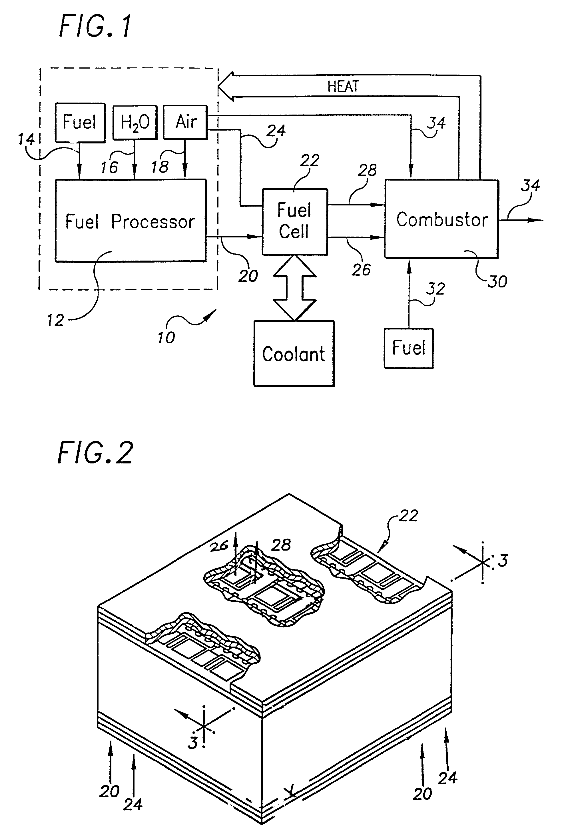
[0036]The invention may be further understood with reference to a generic fuel cell system. Therefore, before further describing the invention, a general overview of the system within which the improved fuel cell of the invention operates is provided. A more detailed description of the fuel cell system as it relates to the present invention, is set forth in U.S. application Ser. No. 09 / 541,934 filed on Aug. 31, 2000 which is assigned to General Motors Corporation and the disclosure of which is expressly incorporated by reference herein.

[0037]In the system, a hydrocarbon fuel is processed in a fuel processor, for example, by reformation and preferential oxidation processes, to produce a reformate gas which has a relatively high hydrogen content on a volume or molar basis. Therefore, reference is made to hydrogen-rich or relatively high hydrogen content. The invention is hereafter described in the context of a fuel cell fueled by an H2-rich reformate regardless of the method by which ...


PUM

PropertyMeasurementUnit
pore sizeaaaaaaaaaa
thicknessaaaaaaaaaa
thicknessaaaaaaaaaa

Abstract

A fuel cell of the type having a membrane electrode assembly (MEA) interdisposed between a pair of bipolar plate assemblies. The MEA may have a convoluted configuration to maximize the effective surface area of the MEA for a given planar area. Each bipolar plate assembly includes a gas distribution layer of open cell conductive foam material which is divided into a plurality of generally parallel segments to define a plurality of generally parallel porous reactant paths. The segments are defined by selectively varying the porosity of the foam material and/or selectively varying the thickness of the foam material. The foam material may be a conductive graphite foam media or a conductive metallic foam media. Each bipolar plate assembly further includes a non-porous, conductive separator plate. The bipolar plate assembly distributes the reactant gases delivered via a manifold structure across the face of the MEA. A coolant layer may also be provided utilizing a segmented foam construction similar to that utilized in the gas distribution layers.

Description

CROSS-REFERENCE TO RELATED APPLICATIONS[0001]This application is a continuation-in-part of United States patent application Ser. No. 09 / 651,934 filed on Aug. 31, 2000, now U.S. Pat. No. 6,566,004 issued May 20, 2003 and a continuation-in-part of U.S. patent application Ser. No. 09 / 694,386 filed Oct. 23, 2000 now U.S. Pat. No. 6,663,994, issued Dec. 16, 2003.FIELD OF THE INVENTION[0002]This invention relates to a fuel cell system and more particularly to a system including a fuel cell having a foam gas distribution media with a variable porosity for delivering a gas to the reactive face of a membrane electrode assembly or a coolant through the fuel cell.BACKGROUND OF THE INVENTION[0003]Fuel cells have been used as a power source in many applications including a power source for an electrical vehicle to replace internal combustion engines. In proton exchange membrane (PEM) fuel cells, hydrogen is supplied to the anode of the fuel cell and oxygen is supplied as the oxidant to the catho...

Claims


Application Information

Patent Timeline
Patent Type & Authority Patents(United States)
IPC IPC(8): H01M8/02H01M8/04H01M8/06H01M8/10H01M8/24H01M16/00
CPCH01M8/0228H01M8/0232H01M8/0234H01M8/0258H01M8/0267H01M8/1002H01M8/241H01M8/2415H01M16/006H01M8/023Y02E60/521H01M8/04029H01M8/04074H01M8/0612H01M2300/0082H01M8/1007Y02E60/50Y02E60/10H01M8/2418
Inventor FLY, GERALD WBRADY, BRIAN K
Owner GM GLOBAL TECH OPERATIONS LLC
Why Eureka
Try Eureka