Head up displays

a display and head technology, applied in the field of head up displays, to achieve the effect of facilitating practical physical size, increasing the size of the region, and small optical package siz

Inactive Publication Date: 2012-09-06
LIGHT BLUE OPTICS
View PDF0 Cites 322 Cited by
  • Summary
  • Abstract
  • Description
  • Claims
  • Application Information

AI Technical Summary

Benefits of technology

[0022]To address this we employ exit pupil expander optics to increase the etendue of the head-up display (HUD), to increase the size of the region over which the displayed imagery may be viewed.
[0023]The inventors have recognised that a further advantage of this approach, in broad terms, the eyebox size of the HUD is decorrelated from the image source etendue, which in turn enables a relatively small optical package size because small optical elements can be employed for image magnification. This optical architecture in its turn facilitates a practical physical size for a system in which the virtual image is moved well beyond 2 m-2.5 m, to at least 5 m, more preferably at least 6 m, 10 m, 30 m, 50 m, or where the virtual image is substantially at infinity. This is advantageous because in a system where a substantially 2D virtual image is displayed in a virtual image plane at such a from the driver, the depth of the perceived distance of portions of the symbology can manipulated. Because the virtual image is a long way away from the viewer the binocular cues are effectively removed, and this enables monocular cues to then be applied to control the perceived distance of portions of the symbology—there is no need to fight against binocular cues. For this reason, also, preferred embodiments of the system employ monocular cues to change the perceived distance of the virtual image, more particularly to bring portions of the symbology graphics of the displayed virtual image towards the driver/viewer although the actual distance of the virtual image plane from the driver/viewer (sometimes called the collimation distance) remains fixed.
[0024]In preferred embodiments of the contact analogue HUD the exit pupil expander optics are configured to provide a (horizontal or vertical) field of view for the virtual image of at least 5 degrees, more preferably at least 8 degrees or 10 degrees. The above described optical architec

Problems solved by technology

The use of a laser-based virtual image generator system provides particular advantages

Method used


Image

  • Head up displays
  • Head up displays
  • Head up displays

Examples


Embodiment Construction

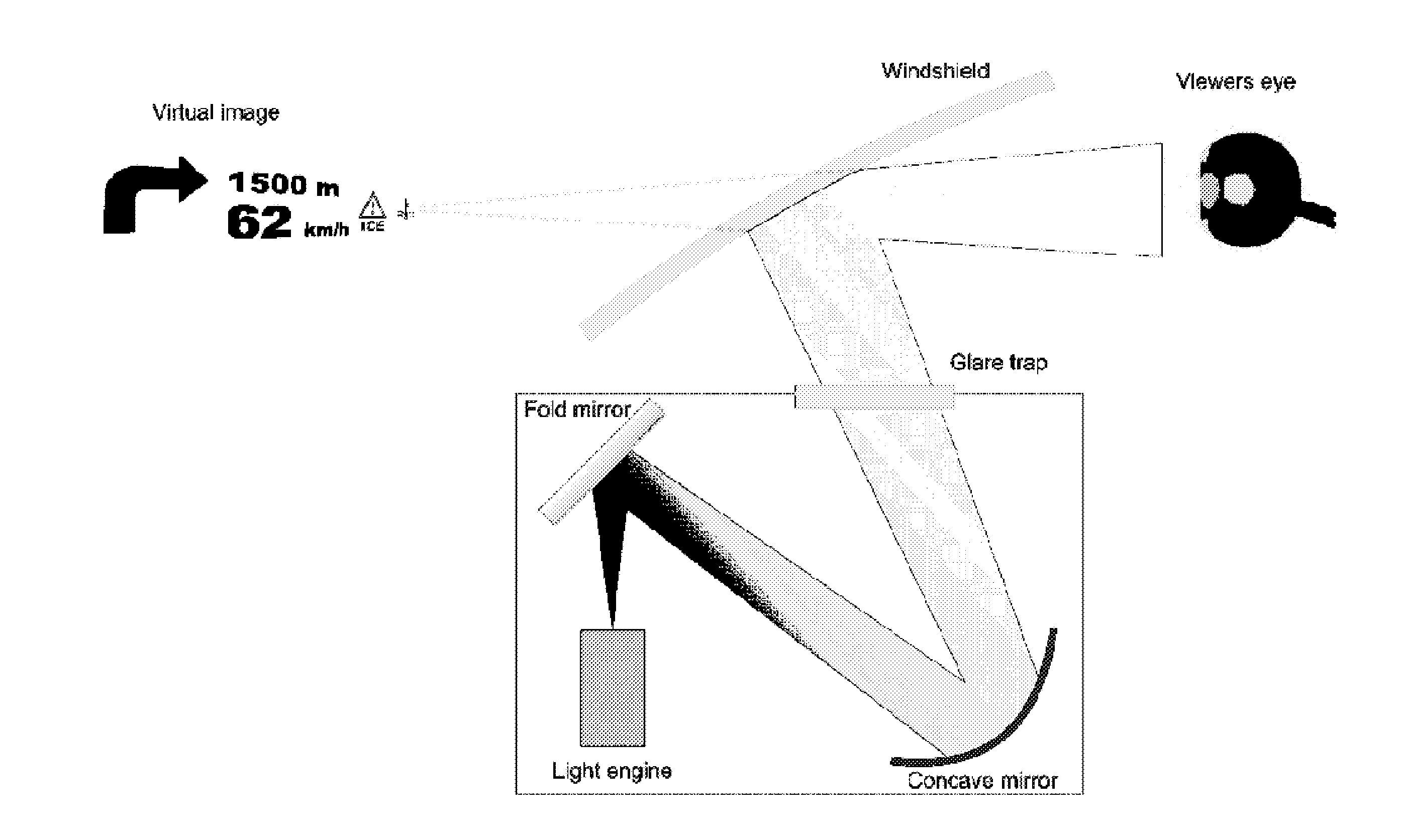
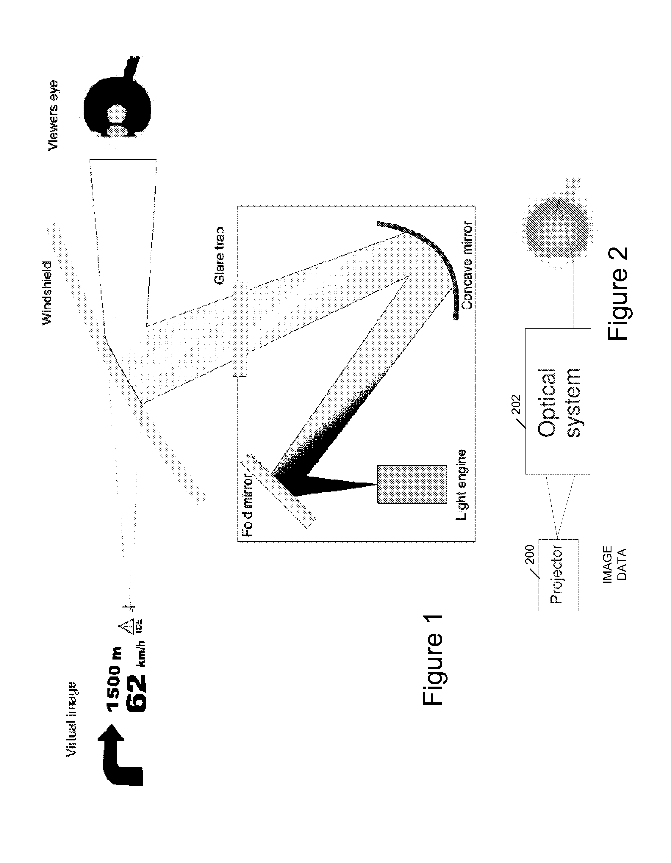
[0089]A virtual image display provides imagery in which the focus distance of the projected image is some distance behind the projection surface, thereby giving the effect of depth. A general arrangement of such a system includes, but is not limited to, the components shown in FIG. 2. A projector 200 is used as the image source, and an optical system 202 is employed to control the focus distance at the viewer's retina 204, thereby providing a virtual image display.

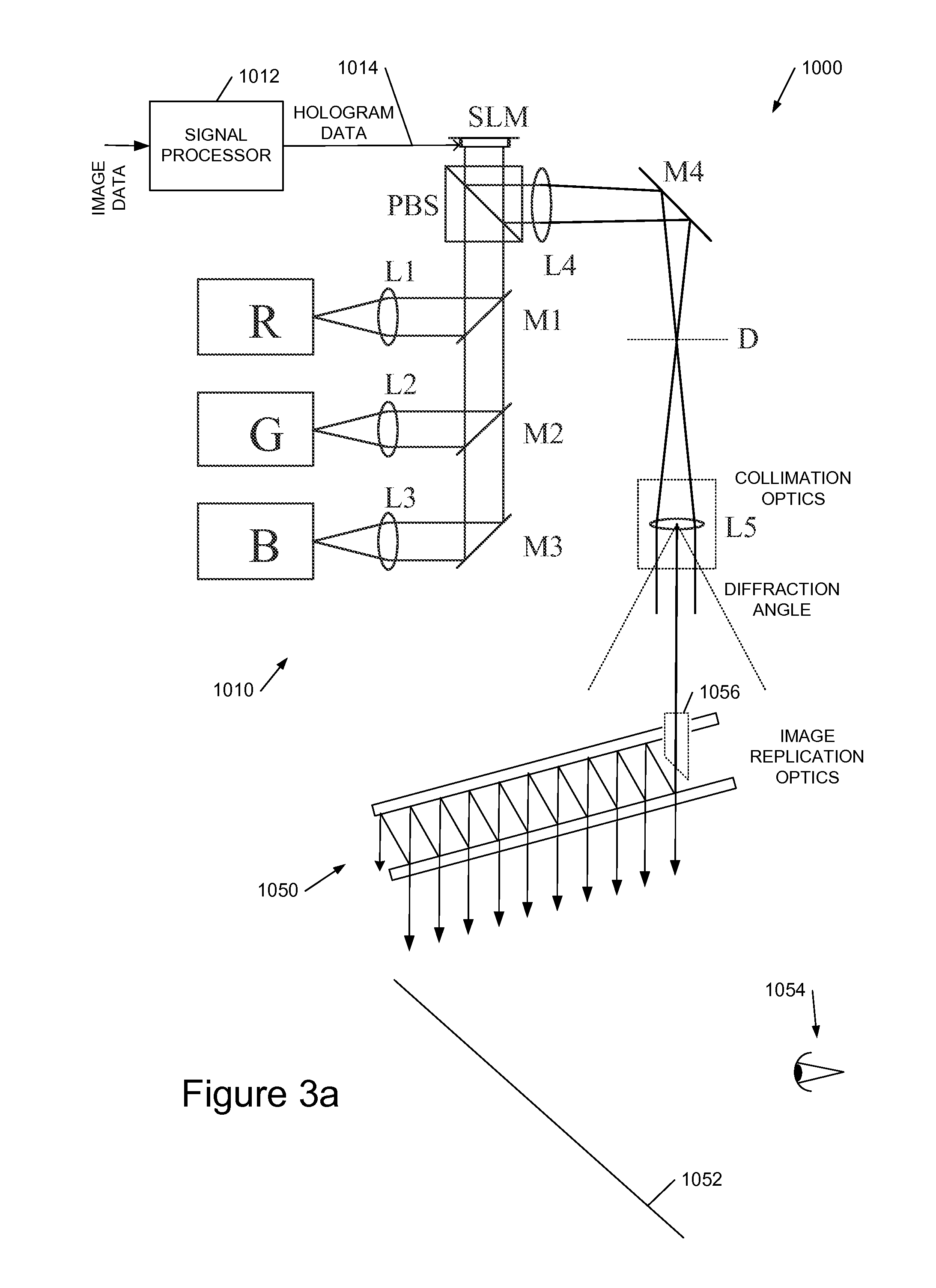
[0090]To aid in understanding background and context for the description of preferred embodiments of the head up display systems we describe it is helpful first to outline one example of a preferred head up display, although use of an HUD of this type is not essential. The HUD we will describe uses a laser-based system to generate an image for display, more particularly an image generator which generates an image by calculating a hologram for the image and displaying this on an SLM. The skilled person will, however, apprec...


PUM


Abstract

We describe a road vehicle contact-analogue head up display (HUD) comprising: a laser-based virtual image generation system to provide a 2D virtual image; exit pupil expander optics to enlarge an eye box of the HUD; a system for sensing a lateral road position relative to the road vehicle and a vehicle pitch or horizon position; a symbol image generation system to generate symbology for the HUD; and an imagery processor coupled to the symbol image generation system, to the sensor system and to said virtual image generation system, to receive and process symbology image data to convert this to data defining a 2D image for display dependent on the sensed road position such that when viewed the virtual image appears to be at a substantially fixed position relative to said road; and wherein the virtual image is at a distance of at least 5 m from said viewer.

Description

FIELD OF THE INVENTION[0001]This invention relates to improved Head Up Displays (HUDs), more particularly to so-called contact analogue HUDs, and to light shields for HUDs, for inhibiting both reflections from incoming light such as sunlight and damaging injection of light into the projection optics.BACKGROUND TO THE INVENTION[0002]Automotive head-up displays (HUDs) are used to extend the display of data from the instrument cluster to the windshield area by presenting a virtual image to the driver. An example is shown in FIG. 1, in which lens power provided by the concave and fold mirrors of the HUD optics form a virtual image displayed at an apparent depth of around 2.5 m. Such virtual images are typically presented an at apparent distance of between 2 m and 2.5 m from the viewer's eyes, thereby reducing the need to re-accommodate focus when transitioning between displayed driving information and the outside world. This method of presenting data also reduces the amount of visual sc...

Claims


Application Information

Patent Timeline
IPC IPC(8): H04N7/18G09G5/00
CPCG01C21/365G03H2001/2239G02B6/00G02B27/01G02B2027/0118G02B2027/0123G02B2027/0138G02B2027/014G03H1/2249G03H1/2294G03H2001/2284G03H2227/02G03H1/2205G03H2223/16G03H2223/24G02B5/20G06F3/147G09G3/002G09G5/14G09G2380/10G09G2380/12
Inventor LACOSTE, LILIANSTINDT, DOMINIKBUCKLEY, EDWARD
Owner LIGHT BLUE OPTICS
Why Eureka
Try Eureka