Pliers for forming orthodontic wires

a technology of orthodontic wires and pliers, which is applied in the field of pliers for forming orthodontic wires, can solve the problems of inability to form sharp bends in fully elastic ni—ti wires, interference between the beaks of pliers, and the degree of scuffing of wires

Inactive Publication Date: 2011-06-28
LINDQUIST JOHN T II +1
View PDF40 Cites 239 Cited by
  • Summary
  • Abstract
  • Description
  • Claims
  • Application Information

AI Technical Summary

Benefits of technology

[0028]This invention provides pliers for forming orthodontic wires having opposing beaks with complementary wire-forming surfaces that include interfering portions. A hinge mechanism enables the beaks to open and close by rotating about an axis, and also allows a range of axial motion between the beaks sufficient to prevent interference between the wire-forming surfaces as the beaks are closed. A spring, such as a Belleville washer, exerts a biasing force parallel to the hinge axis to maintain alignment of the beaks, but allows the required range of axial motion between the beaks to prevent interference.

Problems solved by technology

Pliers designed in the past were able to adequately form sharp bends in stainless steel wires, but are generally incapable of forming sharp bends in fully elastic Ni—Ti wire for example.
Another problem is presented by interference between the beaks of the pliers.
The problems that are encountered as higher over-bend angles are incorporated into the beaks are that the degree of scuffing of the wire, and the amount of give or flexing required of the beaks becomes unworkably excessive.
For example, excessive scuffing of the wire can actually shear-off material and significantly scar the wire.
Outward flexing of the pliers' beaks can also lead to rapid wear of the hinge and excessive flexing of the beaks can lead to embrittlement and breakage.

Method used


Image

  • Pliers for forming orthodontic wires
  • Pliers for forming orthodontic wires
  • Pliers for forming orthodontic wires

Examples


Embodiment Construction

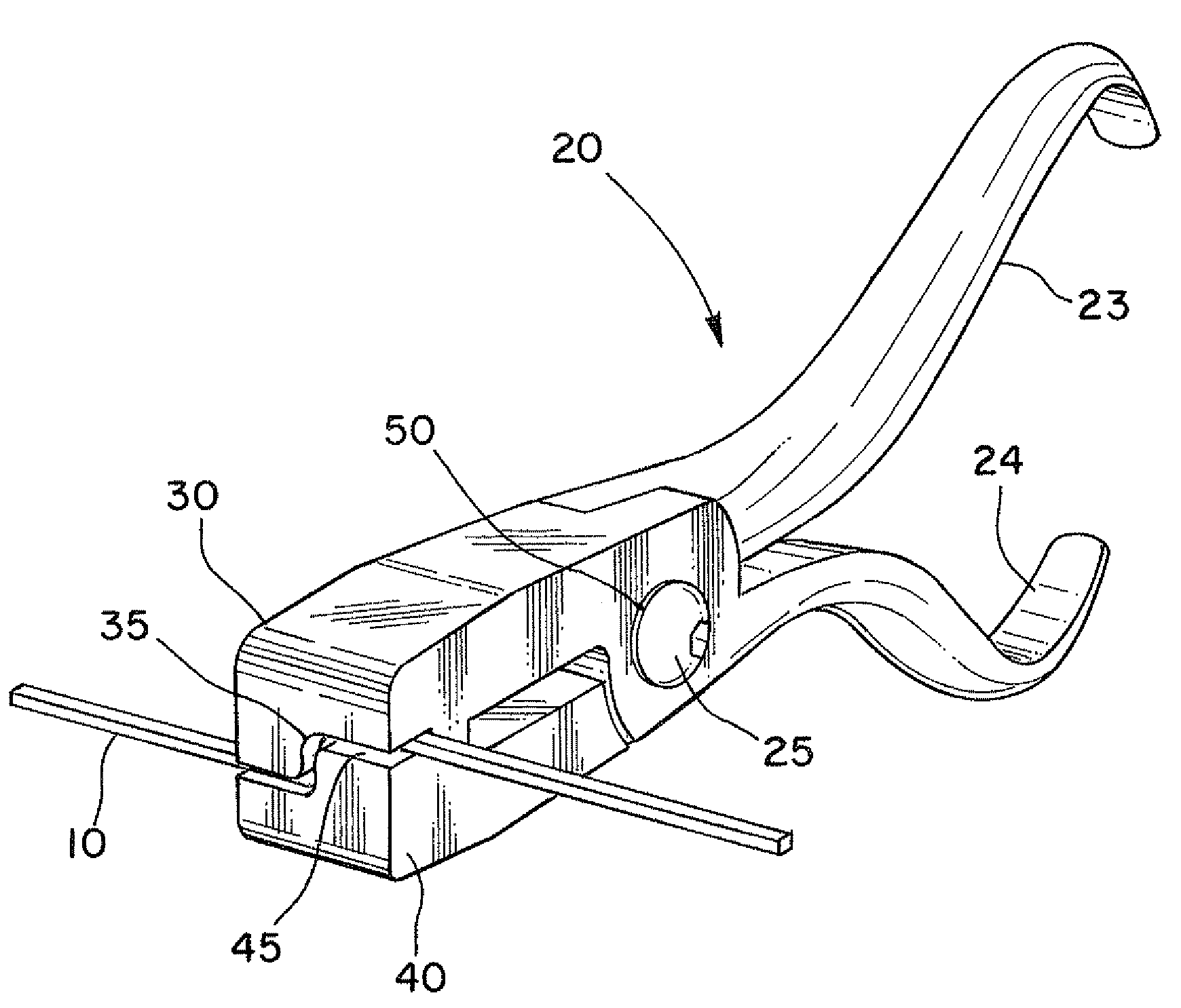
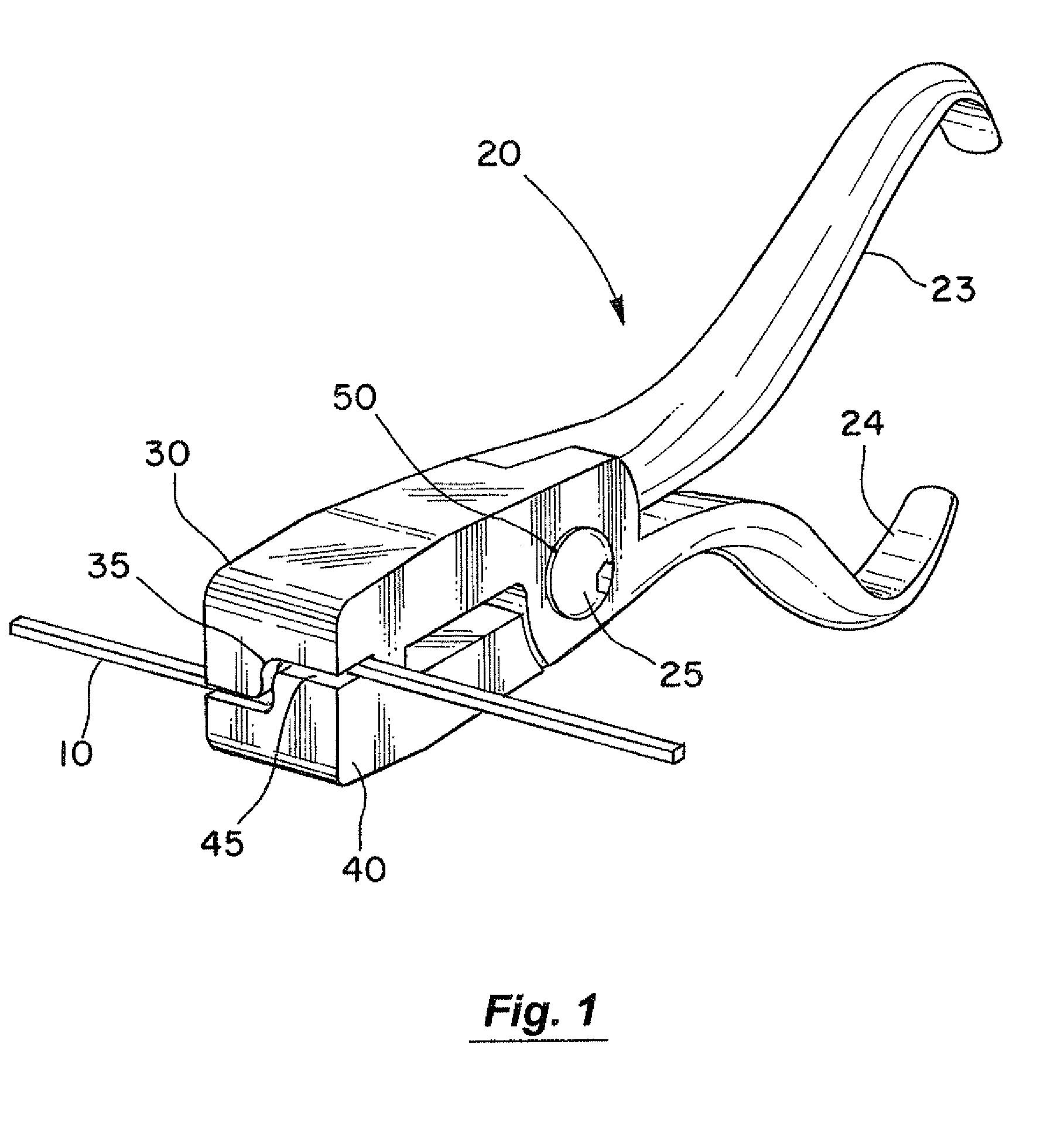
[0051]One embodiment of the present invention is shown in FIGS. 1-4. FIG. 1 is a front perspective view of the pliers 20. FIG. 2 is a detail perspective view with the beaks of the pliers 20 in an open position. FIG. 3 is a detail perspective view of lower beak 40 of the pliers and the formed wire 10. FIG. 4 is a detail perspective view of the pliers 20 with the beaks 30, 40 partially closed. The major components of the pliers 20 are two handles 23, 24 and beaks 30, 40 rotatably connected by a hinge mechanism 25. Each beak 30, 40 can be formed as a single piece with one of the handles 23, 24, as is the case with many conventional pliers.

[0052]The beaks 30, 40 include complementary wire-forming surfaces 35, 45 for forming an orthodontic wire into a predetermined shape. As the pliers 20 are closed, the wire-forming surfaces 35, 45 are brought together to form a channel having the desired shape and dimensions to form a wire. The spacing between the wire-forming surfaces 35, 45 should al...


PUM

PropertyMeasurementUnit
widthaaaaaaaaaa
widthaaaaaaaaaa
biasing forceaaaaaaaaaa

Abstract

A pliers for forming orthodontic wires has opposing beaks with complementary wire-forming surfaces that include interfering portions. A hinge mechanism enables the beaks to open and close by rotating about an axis, and also allows a range of axial motion between the beaks sufficient to prevent interference between the wire-forming surfaces as the beaks are closed. By preventing such interference, novel over-bending capabilities can be achieved to form useful bending of low spring rate wire. A spring, such as a Belleville washer, exerts a biasing force parallel to the hinge axis to maintain alignment of the beaks, but allows the required range of axial motion between the beaks to prevent interference.

Description

BACKGROUND OF THE INVENTION[0001]1. Field of the Invention[0002]The present invention involves the dental specialty of orthodontics and in particular, an improved instrument used to form orthodontic wires.[0003]2. Statement of the Problem[0004]In the broadest sense, the practice of orthodontics can be reduced to the steps of directing carefully regulated corrective forces onto individual teeth. Such forces are typically generated by various types of energy-storing springs that initiate and then maintain the physiological processes supporting tooth movement. The current orthodontic armamentarium includes many configurations of such energy-storing springs, many of which have been developed for specific but common challenges facing orthodontists. The most common energy-storing spring used in nearly all orthodontic treatment methodologies is the archwire. Archwires are formed in the familiar U-shape of the human dental arch. Such wires normally extend around the front of the arch from m...

Claims


Application Information

Patent Timeline
Patent Type & Authority Patents(United States)
IPC IPC(8): A61C7/04
CPCA61C7/04
Inventor LINDQUIST, JOHN THEODORE
Owner LINDQUIST JOHN T II
Why Eureka
Try Eureka