
Zigzag autotransformer apparatus and methods

a technology of transformers and transformers, applied in the direction of fixed transformers, mutual inductances, fixed transformers, etc., can solve the problem of typical cost of efficiency loss

Active Publication Date: 2011-06-28
EATON INTELLIGENT POWER LTD
View PDF11 Cites 5 Cited by
  • Summary
  • Abstract
  • Description
  • Claims
  • Application Information

AI Technical Summary

Benefits of technology

This solution reduces energy losses and supports unbalanced loads with minimal phase shift, increasing energy efficiency and reducing transformer size for a given kVA load, while being compatible with existing power supply configurations.

Problems solved by technology

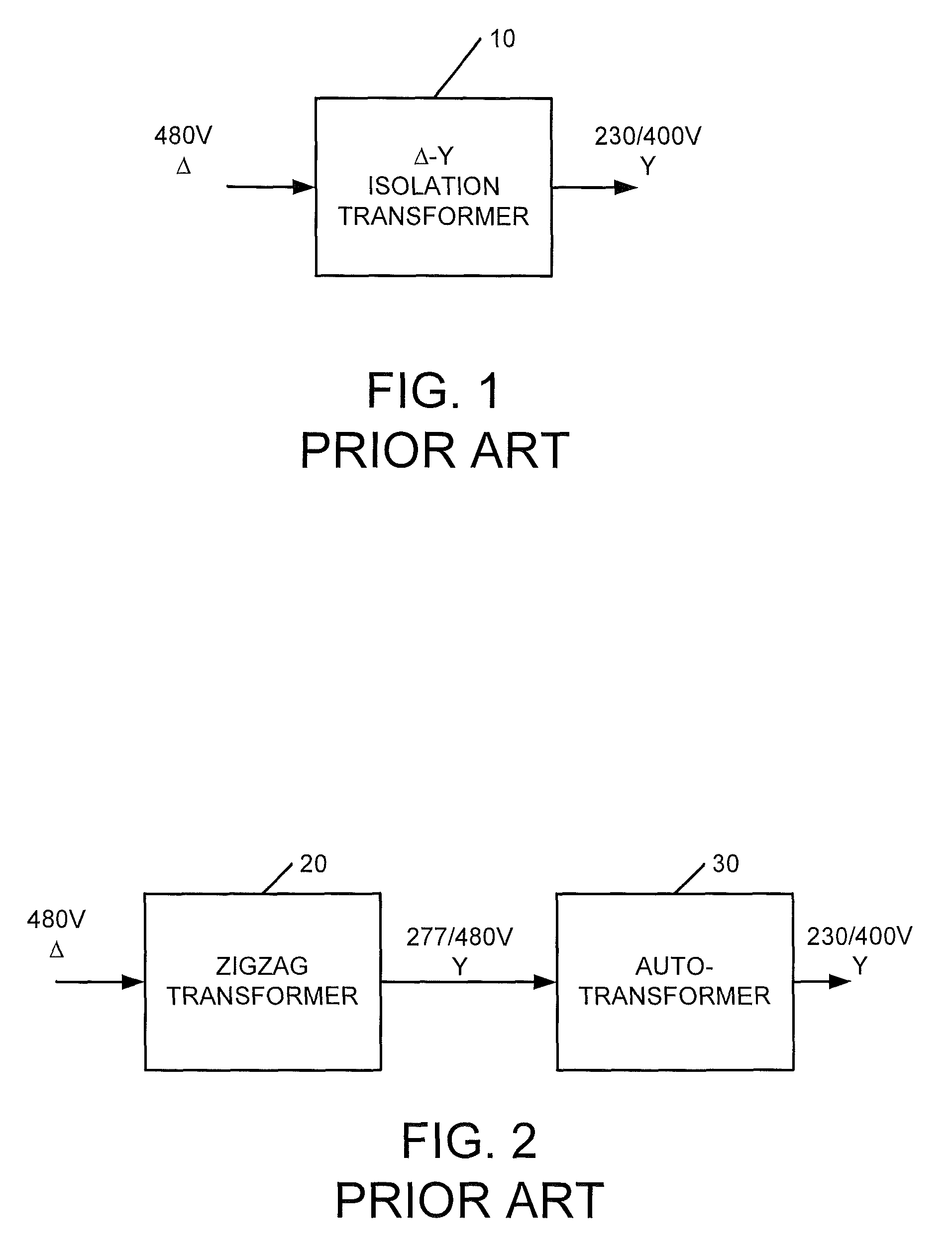
This solution, however, typically comes at the cost of lost efficiency.

Method used


Image

  • Zigzag autotransformer apparatus and methods
  • Zigzag autotransformer apparatus and methods
  • Zigzag autotransformer apparatus and methods

Examples


Embodiment Construction

[0018]Specific exemplary embodiments of the invention now will be described with reference to the accompanying drawings. This invention may, however, be embodied in many different forms and should not be construed as limited to the embodiments set forth herein; rather, these embodiments are provided so that this disclosure will be thorough and complete, and will fully convey the scope of the invention to those skilled in the art. In the drawings, like numbers refer to like elements. It will be understood that when an element is referred to as being “connected” or “coupled” to another element, it can be directly connected or coupled to the other element or intervening elements may be present. As used herein the term “and / or” includes any and all combinations of one or more of the associated listed items.

[0019]The terminology used herein is for the purpose of describing particular embodiments only and is not intended to be limiting of the invention. As used herein, the singular forms ...


PUM

PropertyMeasurementUnit
voltageaaaaaaaaaa
neutral voltageaaaaaaaaaa

Abstract

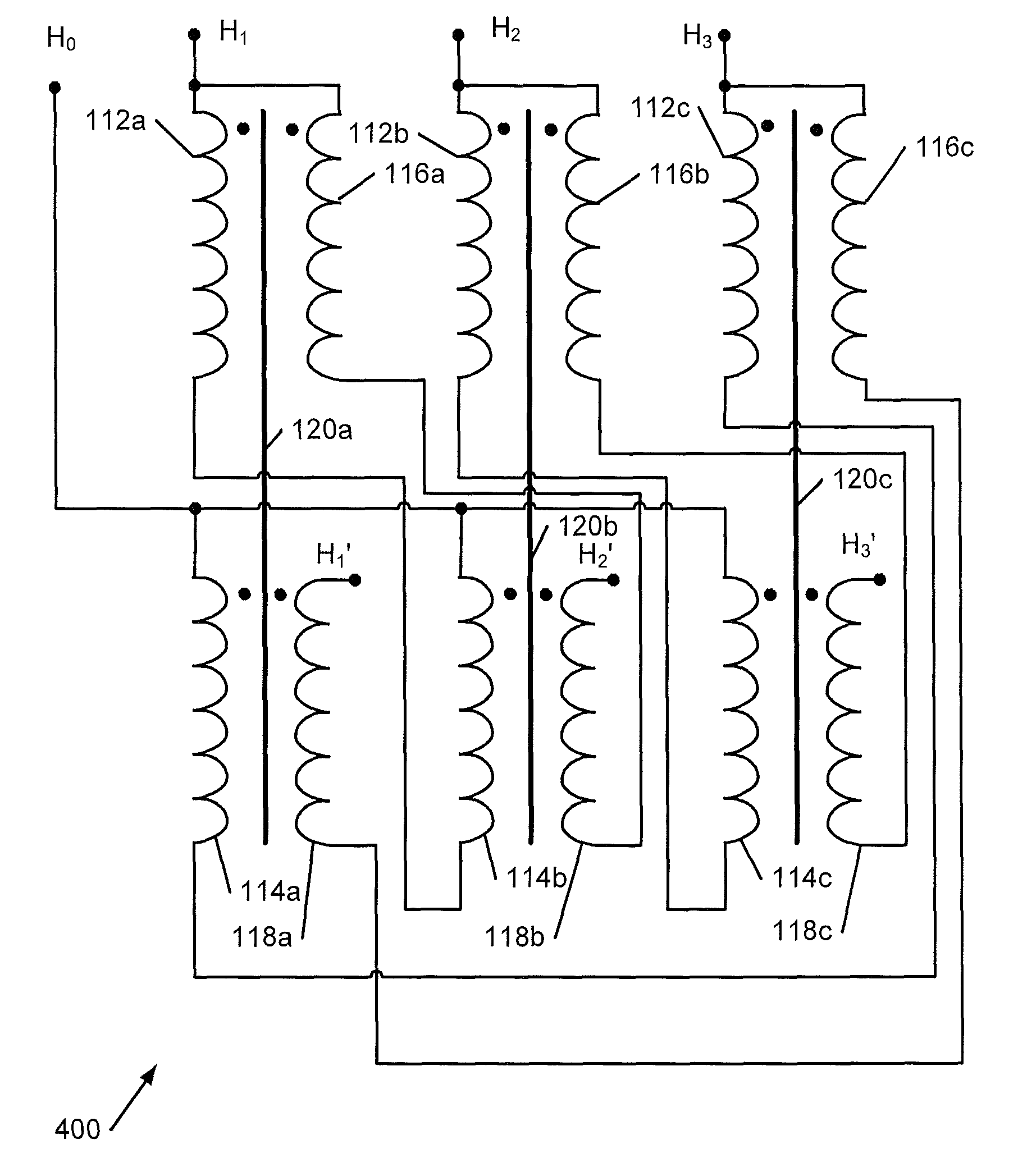
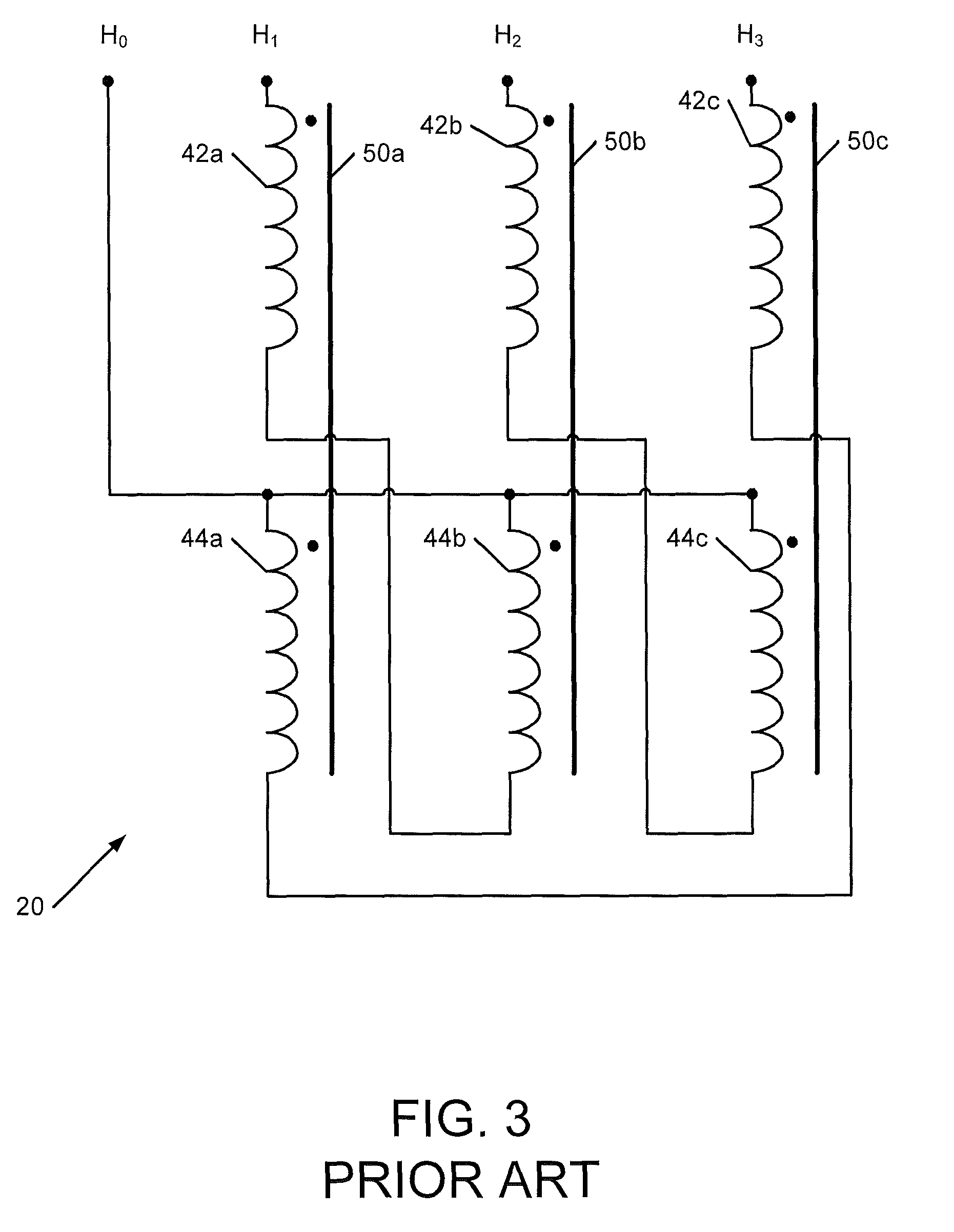
A transformer includes a zigzag transformer comprising first, second and third magnetic cores. The transformer further includes an auxiliary winding set comprising respective pairs of series-connected windings on respective pairs of the first, second and third magnetic cores, the pairs of series-connected windings having respective first terminals connected to respective AC phases of the zigzag autotransformer and respective second terminals configured to provide respective AC output phases.

Description

RELATED APPLICATION[0001]The present application is continuation-in-part of U.S. patent application Ser. No. 12 / 335,940, entitled “Zigzag Autotransformer Apparatus and Methods”, filed Dec. 16, 2008 now U.S. Pat. No. 7,859,376 and claims the priority of U.S. Provisional Patent Application Ser. No. 61 / 163,148, entitled “Zigzag Autotransformer Apparatus and Methods”, filed Mar. 25, 2009, the disclosures of each of which are hereby incorporated by reference herein in their entirety.BACKGROUND OF THE INVENTION[0002]The invention relates to power distribution apparatus and methods and, more particularly, to transformer apparatus and methods.[0003]There is an ongoing quest for increased energy efficiencies in data centers and similar facilities. One technique for increasing efficiency is to increase the voltage used for power distribution in a facility. For example, current computer power supplies commonly can operate from 230V without modification. Replacing a 120 / 208V wye distribution sy...

Claims


Application Information

Patent Timeline
Patent Type & Authority Patents(United States)
IPC IPC(8): H01F17/00H01F27/28H01F30/12
CPCH01F27/38H01F30/12H01F30/02
Inventor JOHNSON, JR., ROBERT WILLIAM
Owner EATON INTELLIGENT POWER LTD
Learn More