Auto-transformer for use with multiple pulse rectifiers

a technology of auto-transformer and pulse rectifier, which is applied in the field of transformers, can solve the problems of adding additional components and adding to the overall cost of the system, and achieve the effect of reducing the cost of the system

Active Publication Date: 2005-02-17
HOWARD INDS
View PDF5 Cites 22 Cited by
  • Summary
  • Abstract
  • Description
  • Claims
  • Application Information

AI Technical Summary

Problems solved by technology

One major limitation with auto-transformers is that they typically do not block the flow of unwanted, zero sequence currents, particularly when the auto-transformers are utilized with multiple pulse rectifier applications.
These additional components necessarily add to the overall cost of the system.

Method used


Image

  • Auto-transformer for use with multiple pulse rectifiers
  • Auto-transformer for use with multiple pulse rectifiers
  • Auto-transformer for use with multiple pulse rectifiers

Examples


Embodiment Construction

)

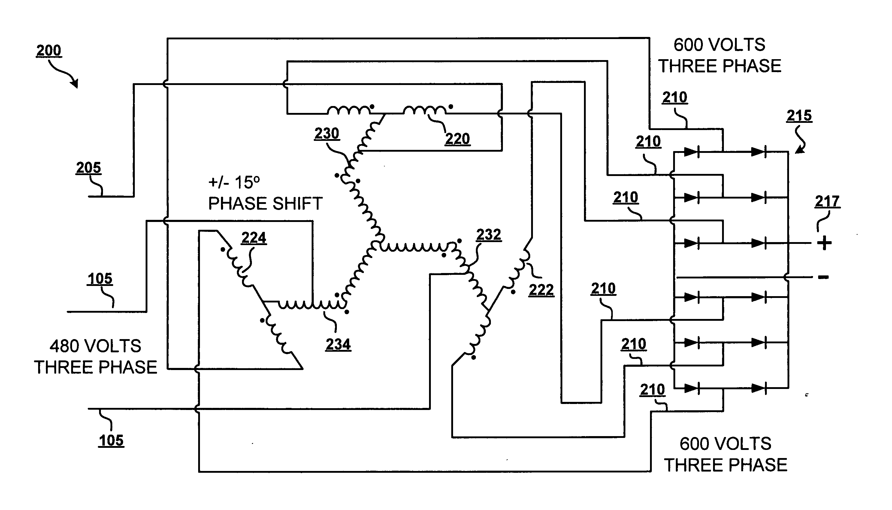
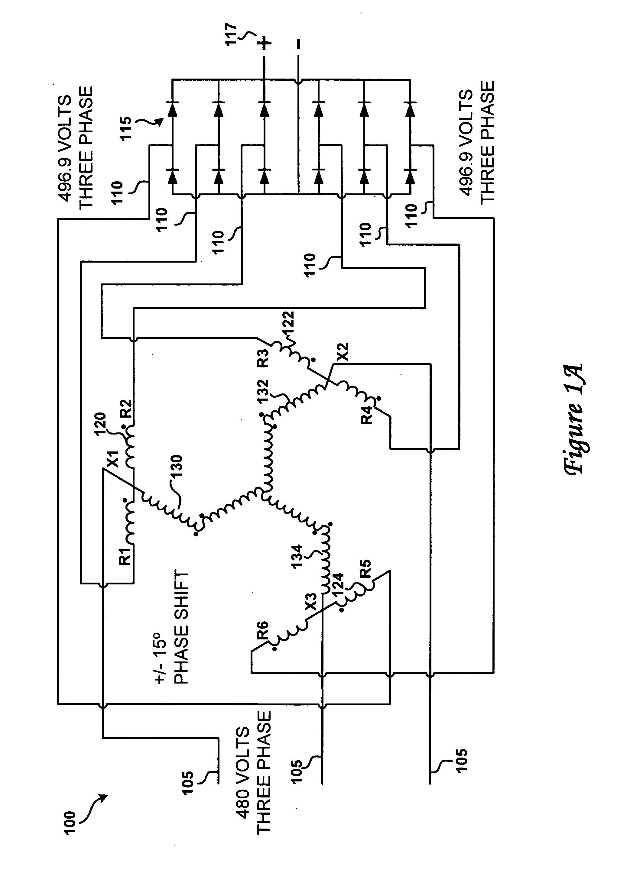
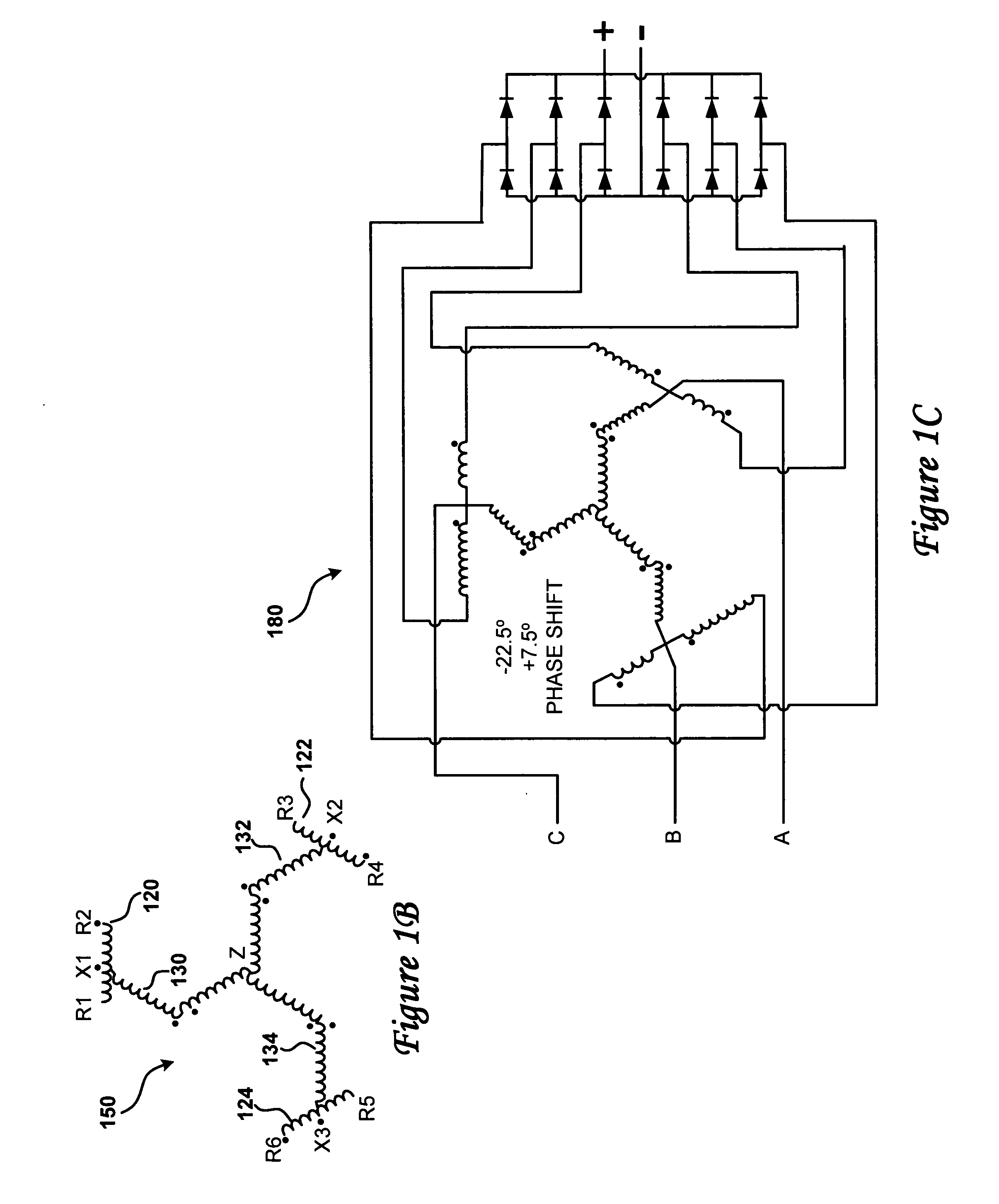
[0022] The invention presents a series of novel designs for zig-zag connected auto-transformers exhibiting the inherent ability to block the flow of zero sequence currents associated with multiple-pulse rectifiers. Various embodiments of the actual auto-transformer designs are illustrated in FIGS. 1A, 1C through 7. However, the functionality of these transformers are made possible through the wiring configuration provided by the coil circuits of FIG. 1B, which provides a zig-zag configuration of coil circuit components, as described below.

[0023] The invention provides a phase shifting auto-transformer designed with inherent ability to block the flow of zero sequence currents associated with twelve pulse rectifiers such as utilized in variable frequency drives. The transformer coils are wound in three separate, multi-wound coils on three single-phase cores. In alternate embodiments, the transformer coils are wound on a four-leg or a five-leg, three-phase core. Notably, the inventio...


PUM

PropertyMeasurementUnit
phase angleaaaaaaaaaa
input voltageaaaaaaaaaa
rated voltageaaaaaaaaaa

Abstract

Zig-zag connected, phase shifting, auto-transformers that provides the inherent ability to block the flow of zero sequence currents that are associated with multiple-pulse rectifiers. The transformer coils are wound in three separate, multi-wound windings on three single-phase cores. A vector oriented winding scheme is provided with three output windings and three internal zig-zag configured pairs of windings. The three internal zig-zag windings are connected at corresponding ends of a first winding to form an electrical neutral. The second windings of the three internal zig-zag windings respectively tap one of the output windings. The external power source connects to a point along each of the second windings of the pair of internal windings.

Description

PRIORITY CLAIM [0001] The present invention claims the benefit of the filing date of U.S. Provisional Patent Application Ser. No. 60 / 494,475, filed on Aug. 12, 2003.BACKGROUND OF THE INVENTION [0002] 1. Technical Field [0003] This invention relates generally to transformers and in particular to auto-transformers for phase shifting. Still more particularly, the present invention relates to auto-transformer for use with multiple pulse rectifiers. [0004] 2. Description of the Related Art [0005] The operation, design, and functionality of basic auto-transformers are generally known in the art. For example, it is well known in the art that auto transformers can transform electric energy using less mass of conductor and core than equivalent isolation transformers. [0006] One major limitation with auto-transformers is that they typically do not block the flow of unwanted, zero sequence currents, particularly when the auto-transformers are utilized with multiple pulse rectifier applications...

Claims


Application Information

Patent Timeline
Patent Type & Authority Applications(United States)
IPC IPC(8): H01F30/02H01F30/12H02M7/08
CPCH01F30/02H02M7/08H01F30/14H01F30/12
Inventor OWEN, DONALD W.
Owner HOWARD INDS
Why Eureka
Try Eureka