Power factor correction converter and power factor correction conversion equipment

一种功率因数校正、转换器的技术,应用在交流功率输入变换为直流功率输出、直流功率输入变换为直流功率输出、输出功率的转换装置等方向,能够解决转换效率和功率密度低等问题,达到提高转换效率、减小纹波、电感量减少的效果

Active Publication Date: 2011-12-28
HUAWEI DIGITAL POWER TECH CO LTD
View PDF4 Cites 24 Cited by
  • Summary
  • Abstract
  • Description
  • Claims
  • Application Information

AI Technical Summary

Problems solved by technology

[0004] Embodiments of the present invention provide a power factor correction converter and a power factor correction conversion device, which solve the technical problems of low conversion efficiency and low power density in the prior art

Method used


Image

  • Power factor correction converter and power factor correction conversion equipment
  • Power factor correction converter and power factor correction conversion equipment
  • Power factor correction converter and power factor correction conversion equipment

Examples


Embodiment 1

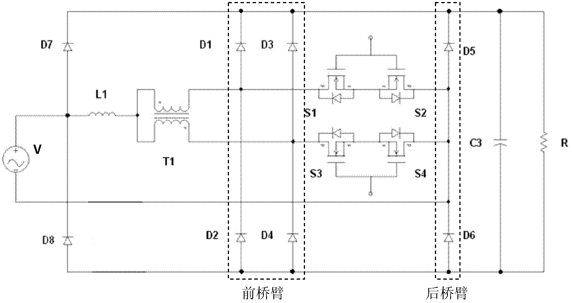
[0027] like figure 1 As shown, the power factor correction converter provided by the embodiment of the present invention has two sets of bidirectional switches S1-S2, S3-S4, because the coil and the front bridge arm of the autotransformer T1 correspond to the bidirectional switches one by one, so In the embodiment of the present invention, both the coil and the front bridge arm of the autotransformer T1 are two, and in order to achieve a better technical effect, an autotransformer T1 with the same number of turns of the two coils is selected.

[0028] As a preferred solution, the power factor correction converter provided in this embodiment further includes a protection bridge arm, and the protection bridge arm includes two protection diodes D7 and D8 connected in series in the same direction, and the middle node between D7 and D8 and the boost inductor L1 The input terminals of the protective bridge arm are connected to each other, and the two ends of the protective bridge ar...

Embodiment 2

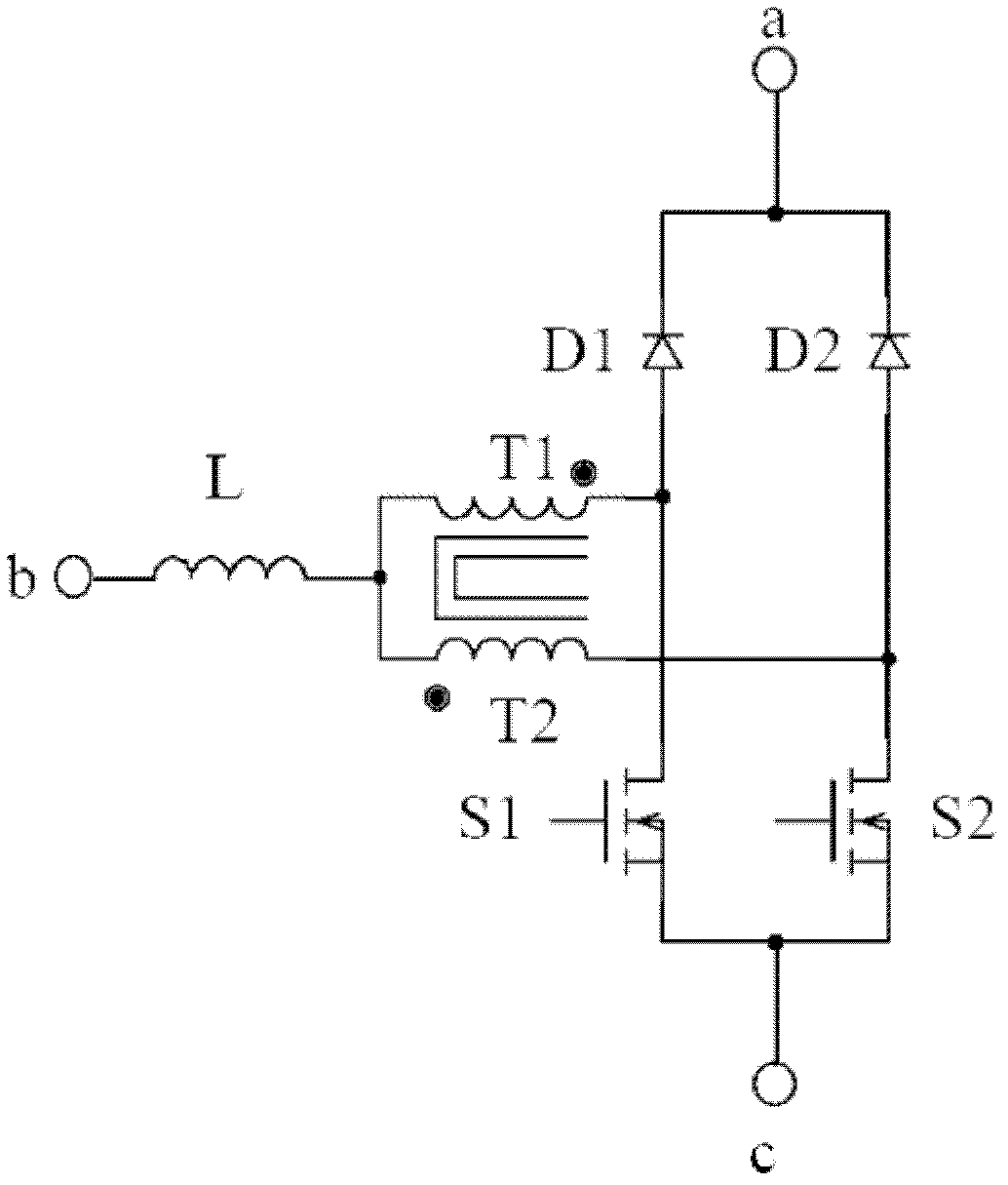
[0051] This embodiment is basically the same as Embodiment 1, the difference is: as Figure 10 As shown, in this embodiment, the boost inductor is integrated in the autotransformer. For low-power applications, the boost inductor can be integrated into the autotransformer, and the required boost inductor value can be obtained by adjusting the coupling coefficient M of the autotransformer, further reducing the size and cost of the converter.

Embodiment 3

[0053] This embodiment is basically the same as Embodiment 1, the difference is: as Figure 11 As shown, in this embodiment, two clamping capacitors C1 and C2 for suppressing common mode noise interference are also included. The other ends of the bit capacitors C1 and C2 are connected and connected to one end of the bus filter capacitor C3. The two clamping capacitors C1 and C2 can suppress electromagnetic interference, especially common-mode noise interference.

[0054] The embodiment of the present invention also provides a power factor correction conversion device, including the above-mentioned power factor correction converter, AC input grid and load; one end of the AC input grid is connected to the rear end of each group of bidirectional switches, and the other end of the AC input grid is connected to the The input terminals of the boost inductor are connected; the two ends of the load are respectively connected with the two ends of the bus filter capacitor corresponding...


PUM


Abstract

An embodiment of the present invention discloses a PFC (Power Factor Correction) convertor and a PFC conversion device, belongs to the technical field of power supply rectification, and solves the technical problems in the prior art that conversion efficiency and power density are low. The PFC convertor comprises at least two sets of bidirectional switches, an autotransformer, a boost inductor, a bus filter capacitor, at least two front axle arms and a back axle arm, wherein a front end of the each set of bidirectional switch is respectively connected with a coil of the autotransformer one to one, a back end of the each set of bidirectional switch is used for connecting to one end of an AC input power network; a center tap of the autotransformer is connected with an output end of the boost inductor, an input end of the boost inductor is used for connecting to the other end of the AC input power network; the front end of the each set of bidirectional switch is respectively connected with the front axle arm, and the back end is connected to the back axle arm; and two ends of the front axle arm and the back axle arm are respectively connected with two ends of the bus filter capacitor correspondingly. The PFC conversion device comprises the PFC convertor. The present invention is applied to power supply rectification.

Description

technical field [0001] The invention belongs to the technical field of power rectification, and in particular relates to a power factor correction converter and a power factor correction conversion device. Background technique [0002] The communication power rectifier module usually adopts a two-stage circuit topology, in which the main function of the front-stage power factor correction (Power Factor Correction; PFC) circuit is to realize power factor correction, and at the same time provide a DC-DC (DC-DC) conversion circuit for the subsequent stage. Stable non-isolated DC high-voltage input (generally 400V) from the power grid, and the subsequent DC-DC conversion circuit converts the non-isolated DC high-voltage isolation into 43-58V DC voltage required by communication equipment. [0003] At present, it is a communication power rectifier module combining interleaving technology and bidirectional switching bridgeless PFC. However, the peak voltage across the boost induc...

Claims


Application Information

Patent Timeline
Patent Type & Authority Applications(China)
IPC IPC(8): H02M1/42H02M7/12H02M7/219
CPCH02M7/219Y02B70/126H02M1/42H02M1/4208H02M7/12H02M1/4225H02M3/1584Y02B70/10Y02P80/10H02M1/0064H02M1/0085
Inventor 潘灯海
Owner HUAWEI DIGITAL POWER TECH CO LTD
Why Eureka
Try Eureka