

Electric switch operation control mode and operation control structure
A technology for electrical switches and control mechanisms, applied in the direction of electric switches, contact operating mechanisms, high-voltage/high-current switches, etc., to achieve the effect of reducing ampere-turns, preventing tripping accidents, and compensating for demagnetization
- Summary
- Abstract
- Description
- Claims
- Application Information
AI Technical Summary
Problems solved by technology
Method used
Image

Examples
Embodiment 1
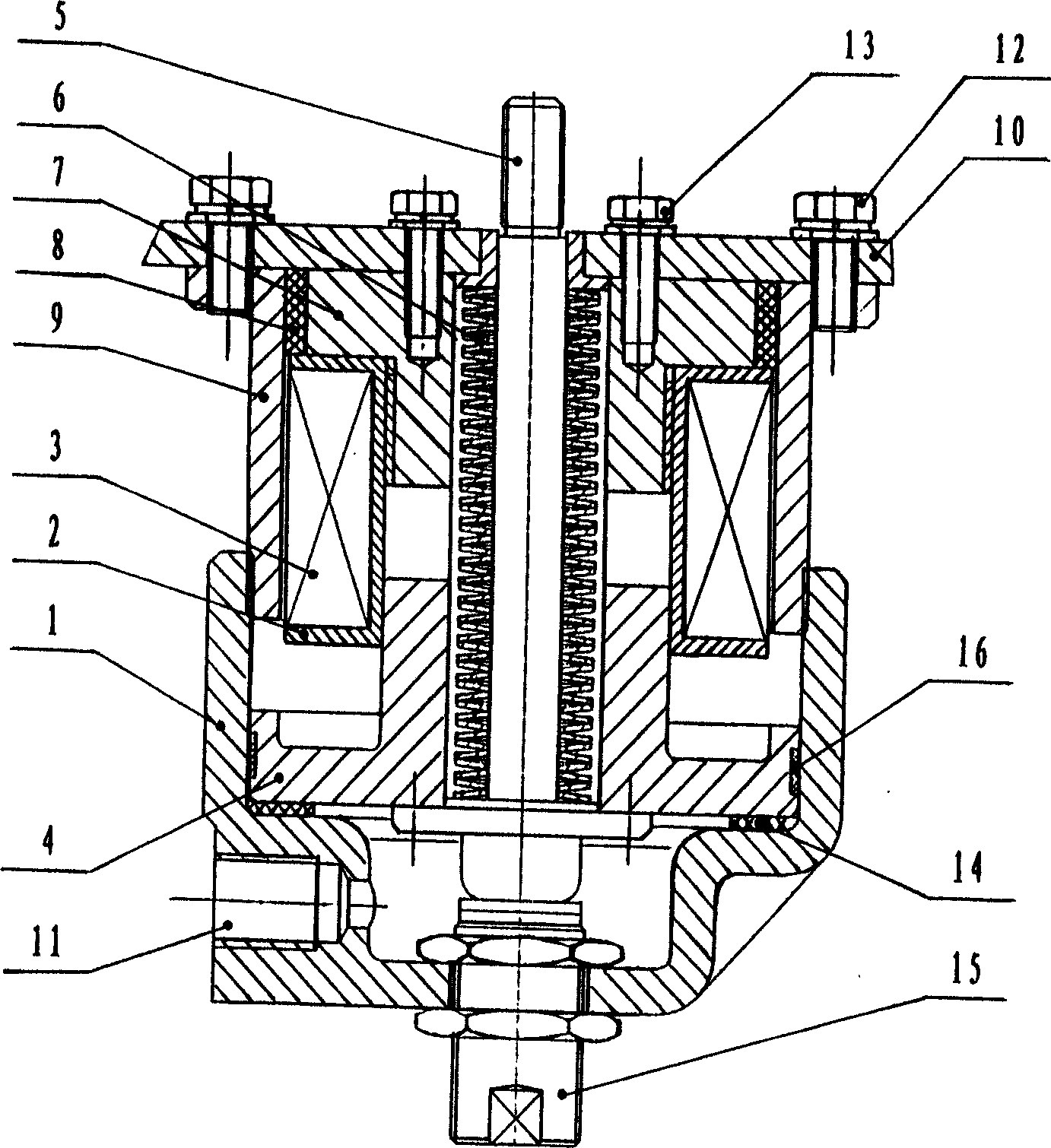
[0028] Embodiment 1: as figure 1 The manipulation control mechanism shown includes transmission cylinder 1, electromagnetic coil frame 2, holding electromagnetic coil 3, piston 4, operating lever 5, opening energy storage spring 6, inner iron core and coil fixing frame 7, permanent magnet 8, The outer iron core 9 and the mounting plate 10; the upper end of the transmission cylinder 1 is threadedly connected with the lower end of the outer iron core 9, and the lower end is provided with an air inlet 11 connected to an external air source; the upper end of the outer iron core 9 and the mounting plate 10 are fastened The parts 12 are fixedly connected; the inner iron core and the coil fixing frame 7, the electromagnetic coil frame 2 and the piston 4 are placed in the cavity formed by the transmission cylinder 1, the outer iron core 9 and the mounting plate 10 from top to bottom, wherein the inner iron core and the The coil fixing frame 7 and the mounting plate 10 are also fixedly...
Embodiment 2
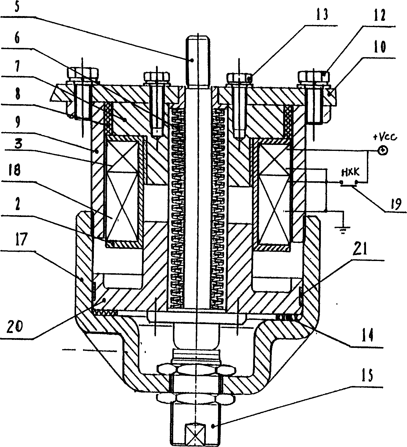
[0033] Embodiment 2: as figure 2 The manipulation control mechanism shown includes a protective cover 17, an electromagnetic coil frame 2, a starting electromagnetic coil 18, a holding electromagnetic coil 3, a closing travel switch 19, a moving iron core 20, an operating lever 5, an energy storage spring 6 for opening, Inner iron core and coil fixing frame 7, permanent magnet 8, outer iron core 9, mounting plate 10; the upper end of the protective outer cover 17 is threadedly connected with the lower end of the outer iron core 9; the upper end of the outer iron core 9 and the mounting plate 10 adopt fasteners 12 Fixed connection; the inner iron core and the coil fixing frame 7, the electromagnetic coil skeleton 2 and the moving iron core 20 are placed in the cavity formed by the protective outer cover 17, the outer iron core 9 and the mounting plate 10 from top to bottom, wherein the inner iron core and the The coil fixing frame 7 and the mounting plate 10 are also fixedly c...
Embodiment 3
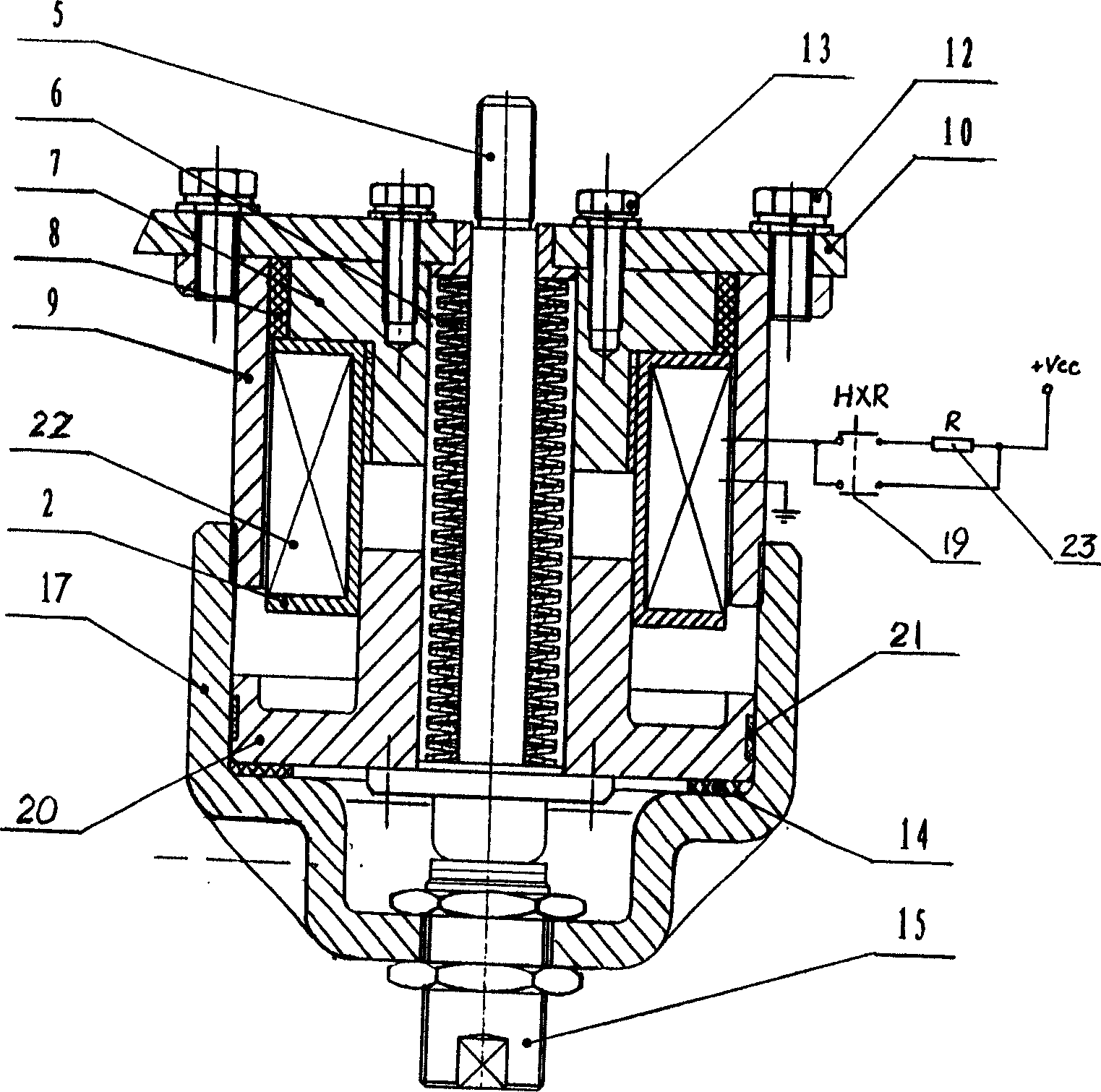
[0038] Embodiment 3: as image 3The manipulation control mechanism shown includes a protective outer cover 17, an electromagnetic coil frame 2, an electromagnetic coil 22, a moving iron core 20, an operating lever 5, an opening energy storage spring 6, an inner iron core and a coil fixing frame 7, and a permanent magnet 8 , outer iron core 9, mounting plate 10, closing travel switch 19, current limiting resistor 23; the upper end of the protective cover 17 is threadedly connected with the lower end of the outer iron core 9; the upper end of the outer iron core 9 and the mounting plate 10 are fixed by fasteners 12 Connection; the inner iron core and the coil fixing frame 7, the electromagnetic coil skeleton 2 and the moving iron core 20 are placed in the chamber composed of the protective outer cover 17, the outer iron core 9 and the mounting plate 10 from top to bottom, wherein the inner iron core and the coil Fixing frame 7 and mounting plate 10 also adopt fastener 13 to fixe...
PUM
 Abstract
Description
Claims
Application Information