Adjustable high-voltage negative ion generating device

A technology for generating devices and negative ions, applied in electrical components and other directions, can solve the problems of wasting energy, insufficient energy efficiency, and reducing efficiency, and achieve the effect of avoiding energy waste

Inactive Publication Date: 2009-03-25
黄思伦 +3
View PDF0 Cites 22 Cited by
  • Summary
  • Abstract
  • Description
  • Claims
  • Application Information

AI Technical Summary

Problems solved by technology

[0003] (1) The amount of negative ions generated is fixed, and it can only be applied to specific receptors to generate negative ions. Therefore, when the receptors change or the environmental conditions change, the negative ion output does not change, resulting in poor negative ion output efficiency or excessive energy. consumption, so that there is a problem of insufficient product efficiency or waste of energy
[0004] (2) Since the high voltage has not been rectified by a diode, although negative ions are output in the form of negative discharge, there will still be a positive half-cycle voltage during the boosting process of the high-voltage coil. Although the voltage energy of the positive half cycle is less than that of the negative half cycle energy, but it will still cause the consumption of negative ions, which will reduce the efficiency
[0005] Therefore, usually in the same environment, when there are many people, there may be more pollution sources, and the amount of negative ions that needs to be used is relatively large, and when there are few people, the amount of negative ions that needs to be used is relatively small; therefore, the above-mentioned prior art The device with fixed output of negative ions cannot adapt to different environments; if the device with fixed output of negative ions is used in larger or smaller space environmental conditions, there will be disadvantages of insufficient energy efficiency or energy waste

Method used


Image

  • Adjustable high-voltage negative ion generating device
  • Adjustable high-voltage negative ion generating device
  • Adjustable high-voltage negative ion generating device

Examples


Embodiment Construction

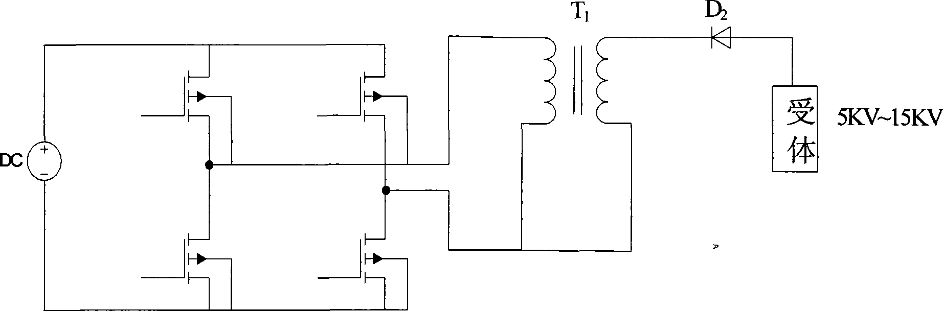
[0031] Such as image 3 As shown, in the first embodiment of the present invention, at least include:

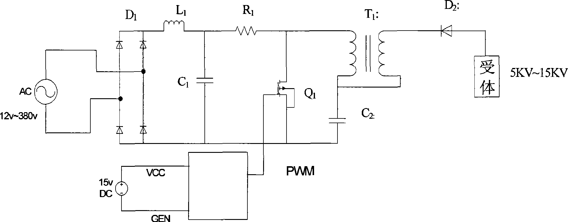
[0032] An input circuit, including a current limiting resistor R1, a power supply, the power supply is an alternating current (AC), and the input circuit also includes a bridge rectifier D1, a filter capacitor C1 and a filter inductor L1;

[0033] A discharge circuit, which at least includes an energy storage capacitor C2, an autotransformer T1, a rectifier diode D2 and a receptor; and

[0034] A pulse width modulation (PWM, Pulse Width Modulation) circuit for controlling the switching tube Q1;

[0035] When powered on, the device adjusts the PWM frequency as required by changing environmental conditions.

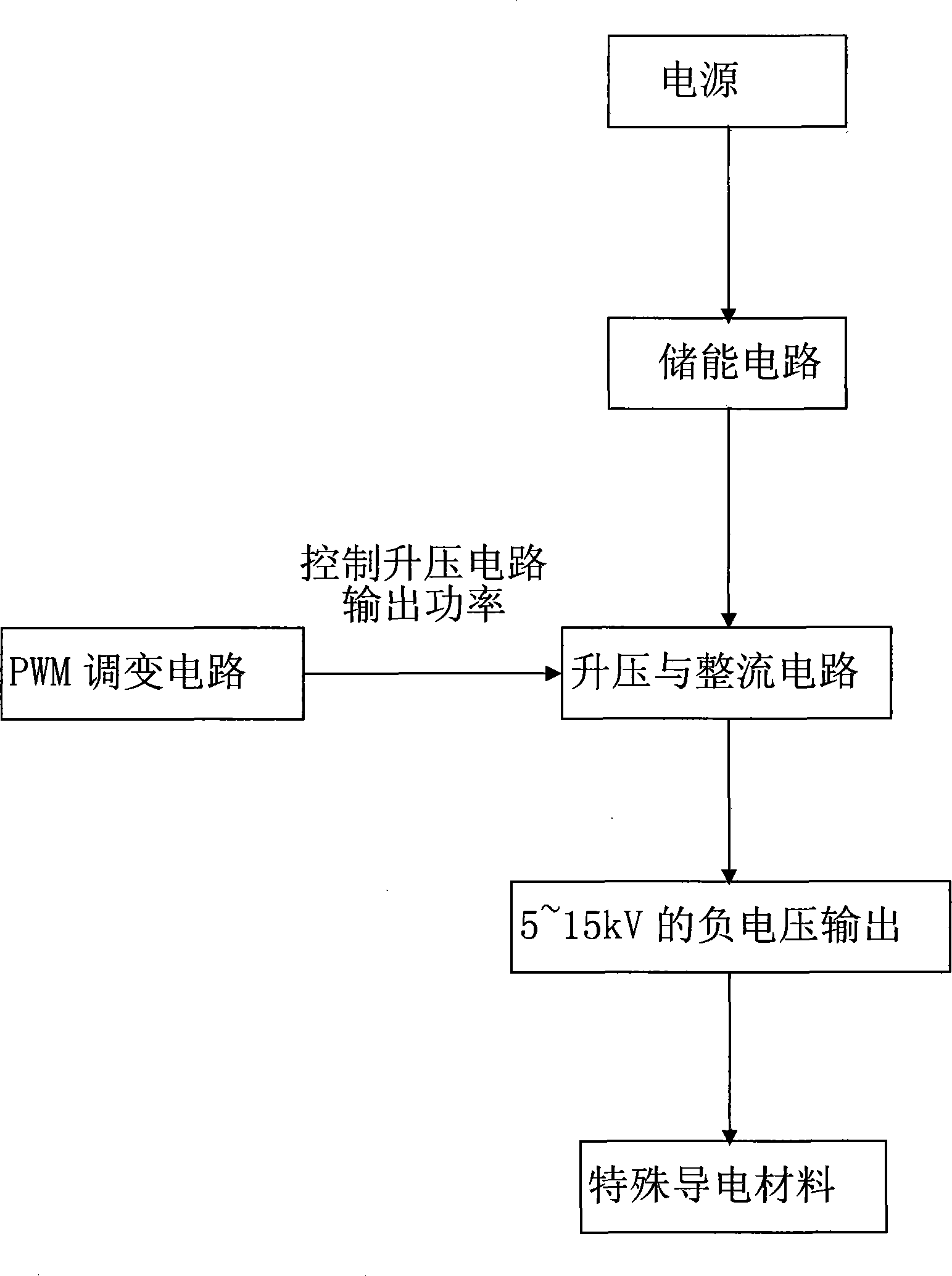
[0036] Above-mentioned a kind of adjustable high voltage anion generating device of the present invention, the main process is as follows figure 2 shown. After the ordinary power supply passes through the energy storage circuit to store the required electric energy, ...


PUM


Abstract

The invention relates to an adjustable high-voltage negative-ion generation device, which comprises an input circuit, a discharge circuit and a pulse width modulation circuit, wherein the input circuit is used for providing power and at least includes a current limiting resistor and a power supply; the discharge circuit is used for generating negative ions and at least includes a switching tube, a storage capacitor, an autotransformer, a rectifier diode and a receptor; and the pulse width modulation circuit is used for controlling the switching tube. When the power supply is plugged in, the device can change pulse width modulation frequency according to the changes of environmental conditions. More electric energy can be stored through a charging circuit, then boosted to a stable high voltage by utilizing a boosting and rectifying circuit, and controlled through the pulse width modulation circuit; the production quantity can be adjusted according to the changes of the environmental conditions, so as to meet actual demands and avoid energy waste.

Description

technical field [0001] The invention relates to a negative ion generating device, and more specifically relates to an adjustable high-voltage negative ion generating device which can adjust the negative ion generating frequency according to different environmental conditions to reduce energy consumption. Background technique [0002] In the prior art, negative ions are generated through a high-voltage circuit to ionize gas molecules in the air, and then decompose harmful gas molecules in the air to achieve the effect of clearing the air. Such as figure 1 As shown, the circuit diagram of a general high-voltage negative ion generating device is rectified by a full-bridge converter and then boosted by an isolation transformer. The receptor only outputs negative ions in the form of negative discharge after the arc is generated. This negative ion generating device operates with a fixed voltage and frequency, which has the following disadvantages: [0003] (1) The amount of nega...

Claims


Application Information

Patent Timeline
Patent Type & Authority Applications(China)
IPC IPC(8): H01T23/00
Inventor 黄思伦蔡宜寿杨正鹏陈丕宏
Owner 黄思伦
Why Eureka
Try Eureka