

Horn antenna
- Summary
- Abstract
- Description
- Claims
- Application Information
AI Technical Summary
Benefits of technology
Problems solved by technology
Method used
Image

Examples
Embodiment Construction
[0032]In all the figures, parts that correspond to one another are provided with the same reference symbols.
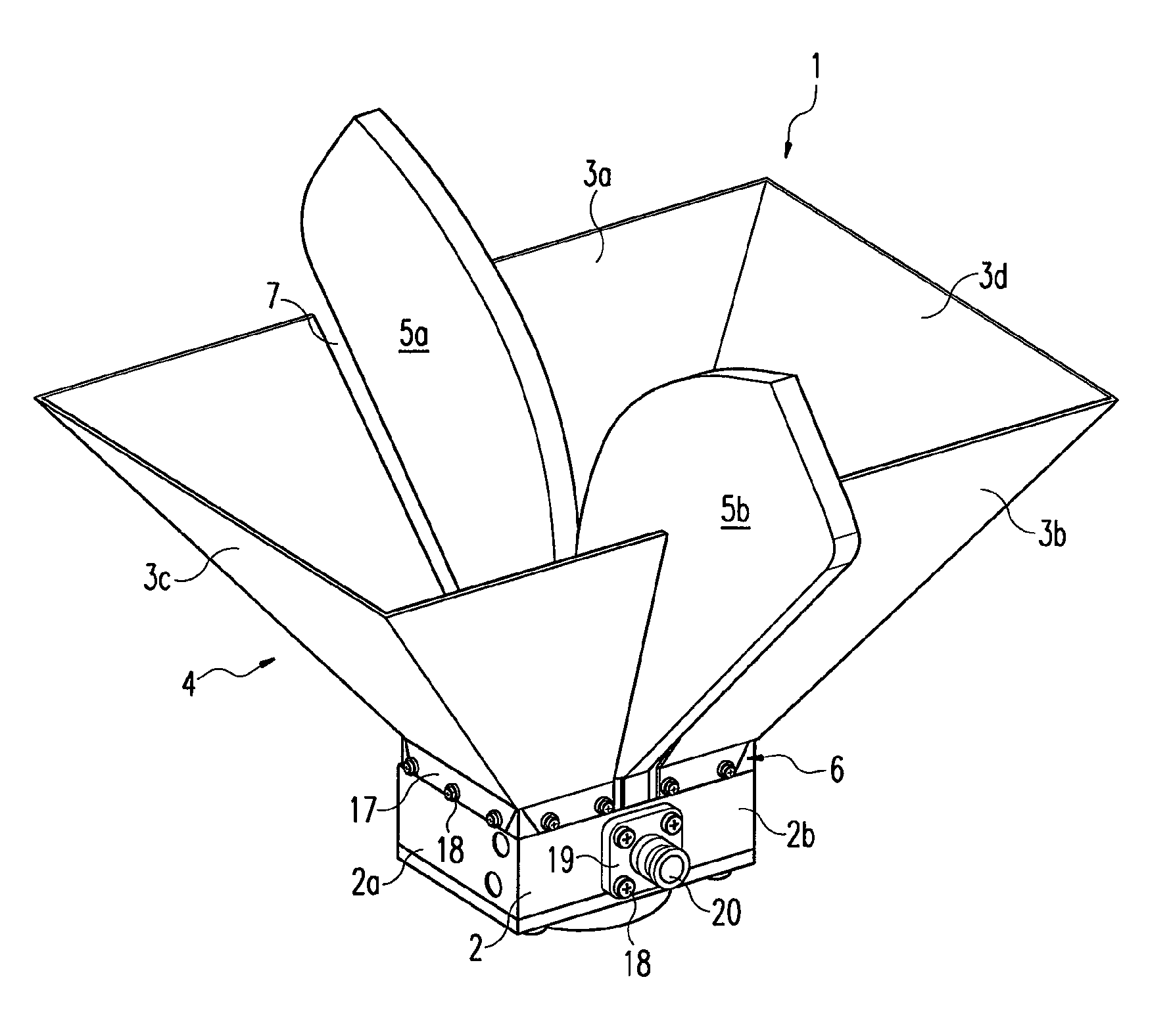
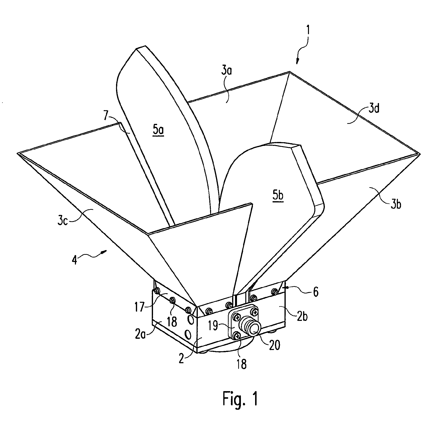
[0033]FIG. 1 shows a side view, in perspective, of a first exemplified embodiment of the antenna 1 according to the invention, from above. The horn funnel 4 of the antenna 1 according to the invention consists of four side walls 3a, 3b, 3c, 3d, two opposed side walls 3a, 3b each having a cutout 7a, 7b through which one of the two fins 5a, 5b extends in each case. Disposed at the narrow end 6 of the horn funnel 4, which funnel is dimensioned, above all, as a reflector at lower frequencies, is the decoupling or coupling apparatus 2a, 2b, the side walls 3a, 3b, 3c, 3d being fastened thereto via a folded edge 17 by means of a number of screws 18 or rivets. In this first exemplified embodiment, the decoupling apparatus 2a and the coupling apparatus 2b are integrated in an overall casing 2. A flange 19 with a coaxial plug 20 is fastened, preferably by means of screws 18, to a side w...
PUM
 Abstract
Description
Claims
Application Information