Method for producing a rollable web and a rollable web

a technology of rollable webs and webs, applied in the field of rollable webs, can solve the problems of chip failure, expensive solution, and inability to work properly with the chip or the antenna, and achieve the effect of avoiding or at least reducing the stress on the chips and the stacking

Inactive Publication Date: 2013-06-18
SMARTRAC INVESTMENT BV
View PDF15 Cites 7 Cited by
  • Summary
  • Abstract
  • Description
  • Claims
  • Application Information

AI Technical Summary

Benefits of technology

[0008]The present invention is based on a method of attaching an integrated circuit (herein a microelectronic chip or chip) on a tag arranged on a rollable substrate web with successive antennas supported by the web, where a chip is attached to an antenna in a predetermined position so that the position of the chip slightly changes in respect of the antenna, when compared to at least some of the chips arranged with individual and successive antennas so that a stacking effect and stress on the chips are avoided or at least reduced in the web roll.
[0009]The aim of the present invention is to create a rollable web with RFID tags comprising antennas and chips, wherein the chips have electrically connected to the antennas within individual and successive tags, and wherein a stacking effect in the web roll and stress on the chips during the rolling of the web are avoided or at least reduced.
[0014]It is advantageous to design the antennas used in webs so that the chips could be positioned into several alternative positions within successive antennas. The number of the possible positions of the chips depends, for example, on the antenna, the materials used and the junction area. There could be, for example, six different positions for a chip. Only a minor change of the position is sufficient, for example 0.5 to 1 mm in the longitudinal direction or in the cross-direction. It is advantageous to use such minor changes between the positions that a chip installing machine could be adjusted to handle the changes in the positions of the chips attached to antennas. Preferably, a position is predetermined, said position defining the order in which the chip installing machine should position the chips onto the antennas for achieving the best result. This order can be systematic, where a position of a chip changes within individual and successive antennas or between successive sequences of antennas or in some combination of these, or the order can be random. Thus, when the position of the chip changes compared to at least some of the chips in appropriate way and with a predetermined position, the chips would not stack within successive web layers of the roll. Even if small position changes of the chip are preferable in view of the typical chip installing machine operation, it is also possible to vary the location of the chips in successive antennas significantly, for example locating the chips in the opposite ends of the successive antennas. Further, it is not necessary to maintain the location of the successive antennas in the web the same, but it is also possible to alter the location or orientation of the antennas on the web. This allows for distributing the chips over a larger area in cross-direction of the web and thus producing a more even cross-directional profile of the roll.
[0015]The method is a cost-effective way to ensure the quality of tags, webs and web rolls and easy to put in to use, because chip installing machines can be adjusted to handle the changes of the positions.

Problems solved by technology

This causes mechanical stress on the chips and results in breaking of the chips, and as a consequence, neither the chip nor the antenna works properly.
However, this is, of course, an expensive way to solve the problem.
This kind of a solution, however, needs more production material and space when storing or transporting these rolls.

Method used


Image

  • Method for producing a rollable web and a rollable web
  • Method for producing a rollable web and a rollable web
  • Method for producing a rollable web and a rollable web

Examples


Embodiment Construction

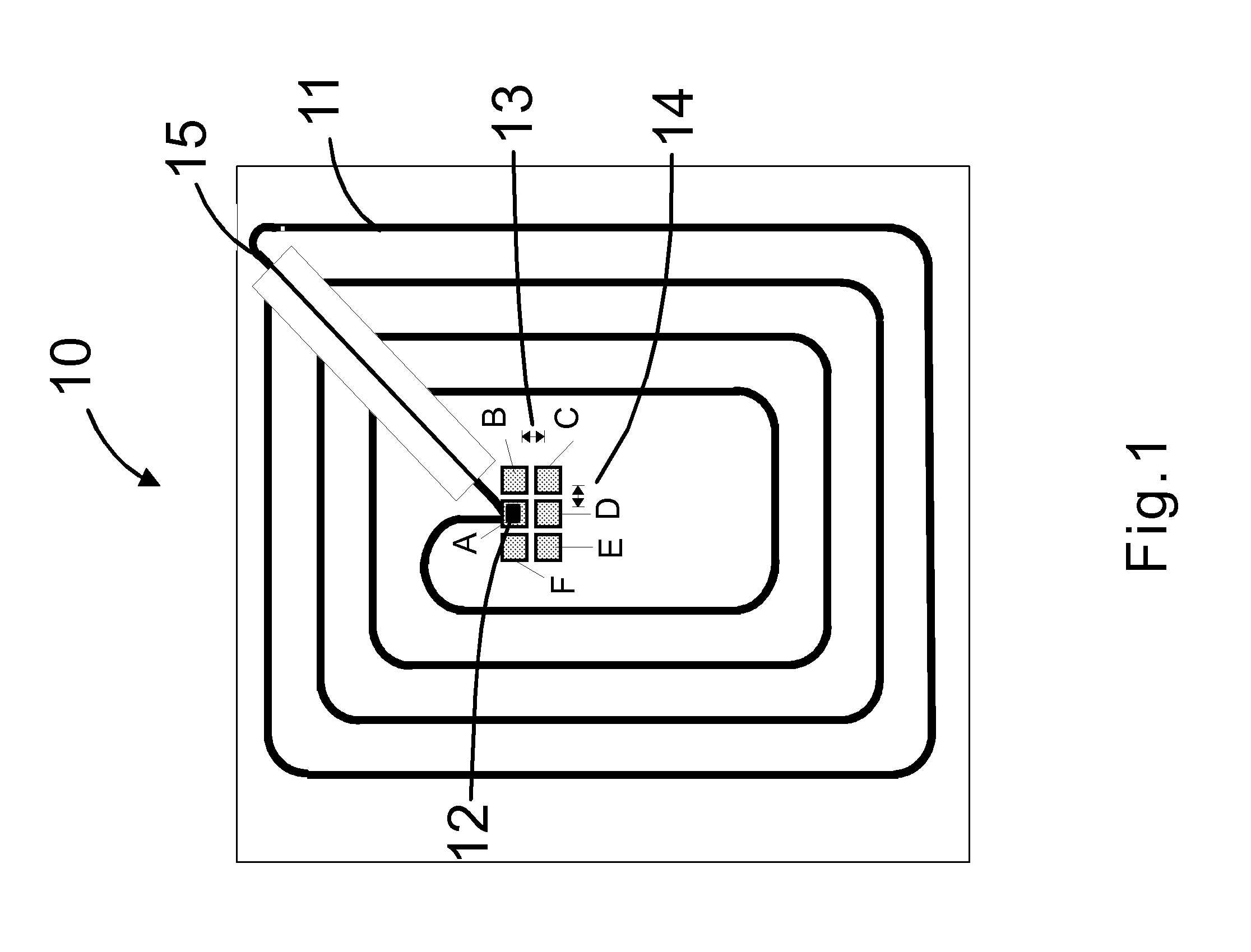
[0020]FIG. 1 shows a front view of one embodiment of the invention. A tag 10 comprising an antenna 11 and an integrated circuit on a chip 12 are formed on the surface of a substrate 15. The chip 12 is attached to the position A of the antenna 11. The antenna 11 is designed so that there are five other alternative positions B-F for attaching a chip 12 to the antenna 11. There should be only a minor chance in the longitudinal direction 13 or in the cross-direction 14 between alternative positions A-F. This change 13 or 14 could be for example 0.5 to 1 mm.

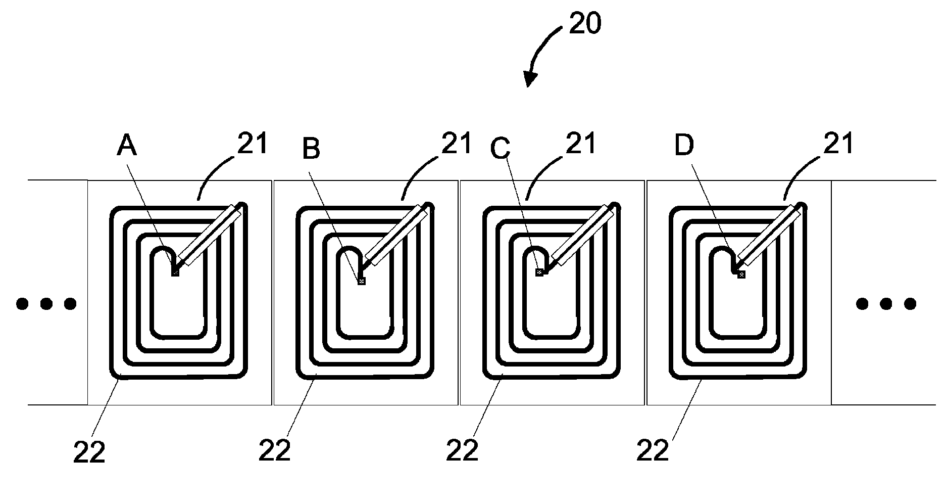
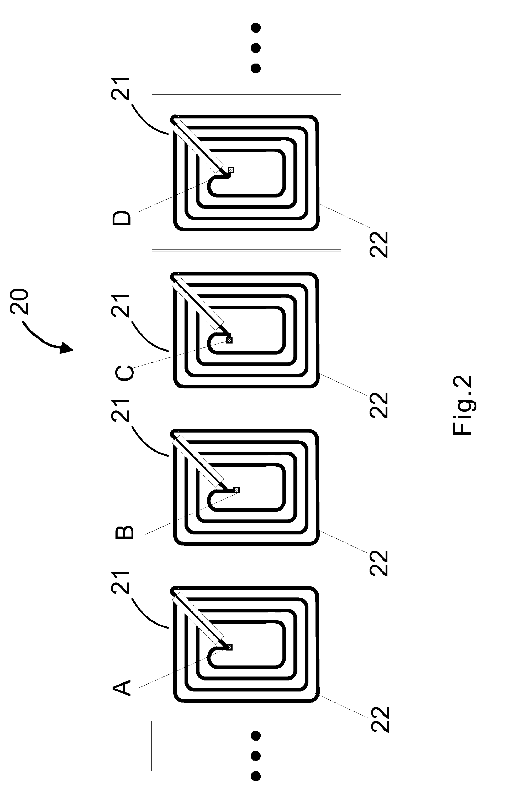
[0021]FIG. 2 shows a front view of one embodiment of the invention. RFID tags 21 are formed on a piece of a long belt-like, rollable, and flexible backing web 20. The tags 21 are formed consecutively, and in each individual tag 21 the position A-D of the chip attached to antenna 22 with a predetermined position has slightly changed in respect of the antenna 22, when compared to the other chips.

[0022]FIG. 3 shows a web roll 30. The web...


PUM

PropertyMeasurementUnit
heightaaaaaaaaaa
mechanical stressaaaaaaaaaa
thicknessaaaaaaaaaa

Abstract

A method for producing a rollable web with successive antennas, where an electronic chip is attached to an antenna in a predetermined position. The position of an electronic chip changes with respect to the antenna when compared to at least some of the chips within individual and successive antennas. A rollable web includes successive antennas, where electronic chips are attached to antennas in a predetermined position. In the rollable web, the position of a chip changes with respect to the antenna compared to at least some of the chips within individual and successive antennas.

Description

CROSS-REFERENCE TO RELATED APPLICATIONS[0001]This application claims priority to Finnish patent application 20085337 filed 21 Apr. 2008 and is the national phase under 35 U.S.C. §371 of PCT / FI2009 / 050288 filed 20 Apr. 2009.FIELD OF THE INVENTION[0002]The present invention relates to a rollable web, the rollable web comprising successive antennas supported by the web and electronic microcircuit chips arranged in connection with said antennas. The invention relates further to a method for producing such a web.BACKGROUND OF THE INVENTION[0003]Radio Frequency Identification (RFID) technology is becoming widely used to identify and control the flow of goods, for instance, to identify packages, pallets and parcels, or RFID tags or tickets or labels (hereafter the term “tag” also covers tickets or labels) are used in conjunction with security-locks in cars and for access control in buildings. Heretofore, RFID tags have been applied to goods in various ways. They may be glued to the article...

Claims


Application Information

Patent Timeline
Patent Type & Authority Patents(United States)
IPC IPC(8): H05K1/00
CPCG06K19/07718G06K19/07749H01Q1/2225H01Q7/00Y10T428/14Y10T29/49018Y10T156/1095Y10T29/49155B65H18/28G06K19/07745H01Q1/2208H05K13/04
Inventor STROMBERG, SAMULI
Owner SMARTRAC INVESTMENT BV
Why Eureka
Try Eureka