Method and system for locating a wave source within a defined area

a wave source and defined area technology, applied in direction finders, instruments, measurement devices, etc., can solve the problems of echoes, emergency vehicles often do not obey traffic rules, emergency vehicles may appear at unexpected locations to other drivers,

Inactive Publication Date: 2011-06-28
TOYOTA MOTOR CO LTD
View PDF16 Cites 5 Cited by
  • Summary
  • Abstract
  • Description
  • Claims
  • Application Information

AI Technical Summary

Problems solved by technology

Furthermore, such emergency vehicles often do not obey the standard traffic rules.
As such, such emergency vehicles may appear at unexpected locations to other drivers of the road.
These previously known systems thus fail to account for reflections, echoes and the like of the sound wave from the emergency vehicle siren and are thus unable to accurately locate the position of the emergency vehicle or other desired detected sound.

Method used


Image

  • Method and system for locating a wave source within a defined area
  • Method and system for locating a wave source within a defined area
  • Method and system for locating a wave source within a defined area

Examples


Embodiment Construction

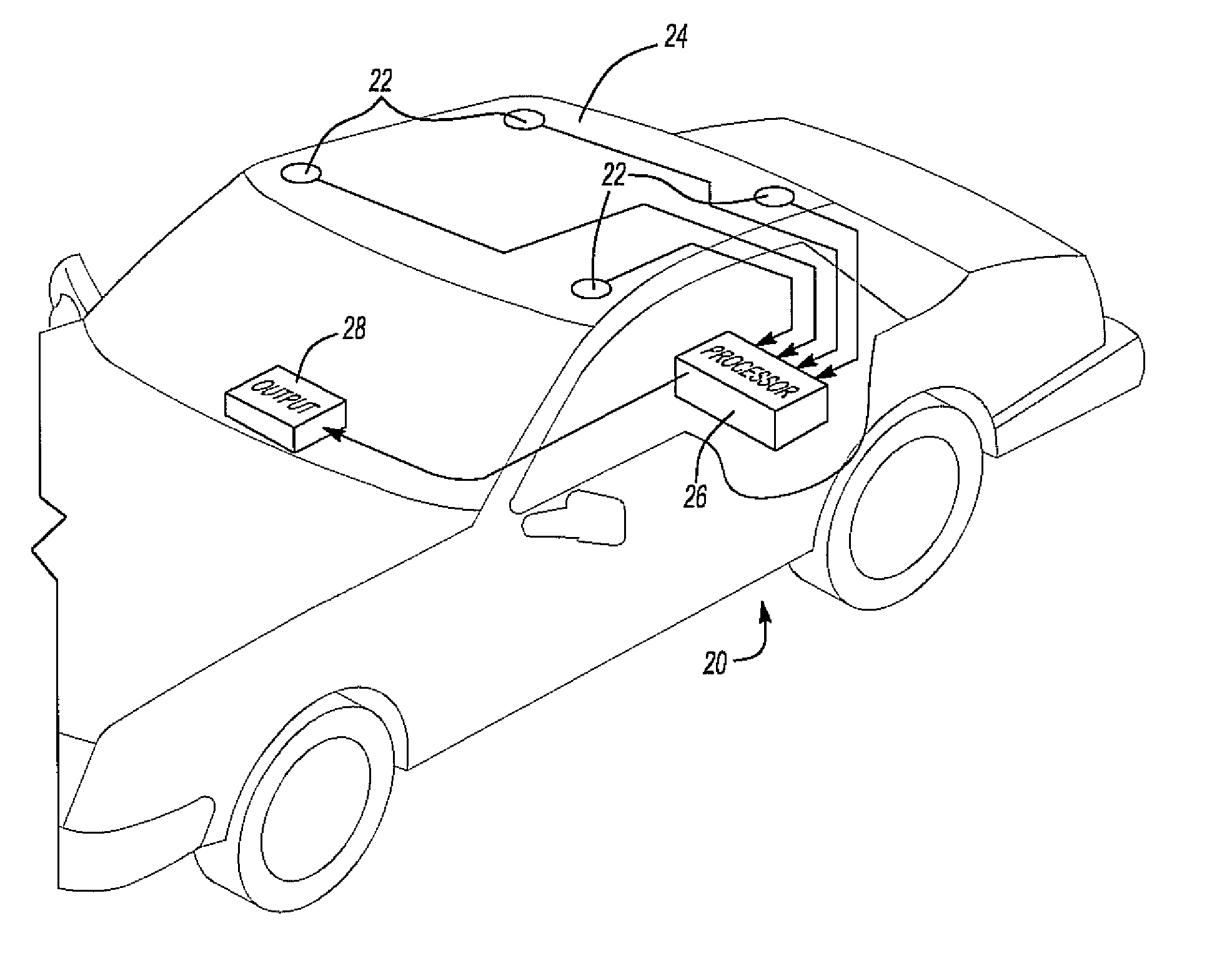
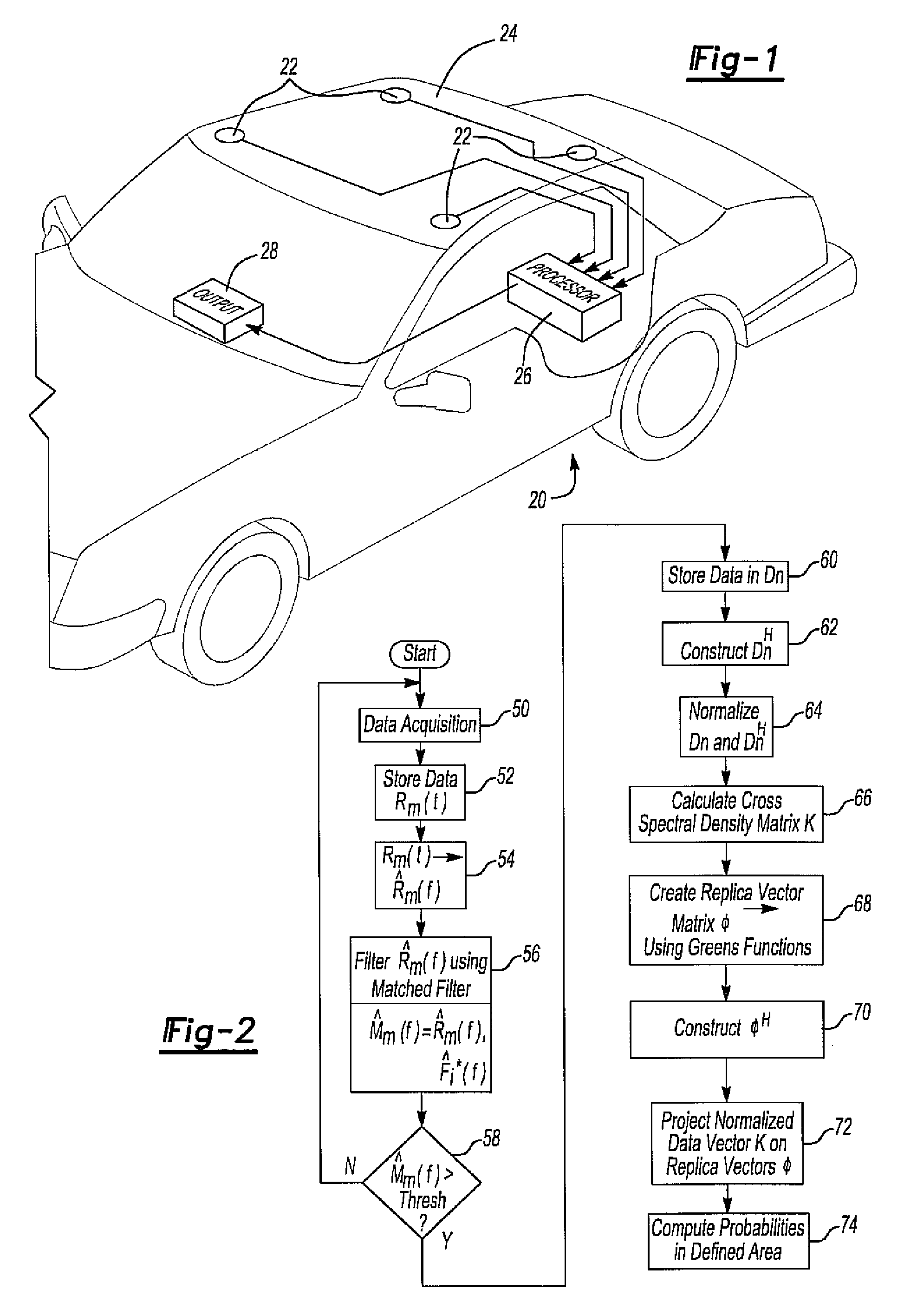
[0017]With reference first to FIG. 1, an exemplary automotive vehicle 20 is shown having at least two and preferably four sound wave receivers or microphones 22 mounted to the vehicle 20 so that the microphones 22 are spaced apart from each other. As shown in FIG. 1, the microphones are shown mounted adjacent each corner of the vehicle roof 24. However, the microphones 22 may be mounted at other locations on the vehicle 20 without deviation from the spirit or scope of the invention.

[0018]Using conventional circuitry, the data outputs from the microphones 22, which correspond to the sound received by each microphone, are connected as input signals to a processor 26. The processor 26, which is preferably microprocessor based, is preprogrammed to process the output signals from the microphones 22 in a fashion that will be subsequently described. The processor 26 also provides an output signal to an output device 28, such as a display screen, or other device.

[0019]With reference now to ...


PUM


Abstract

A method and system for locating a sound source within a defined area in which the sound data is collected with a plurality of spaced apart microphones. The sound data received by the microphones is processed to form a cross spectral density matrix containing vectors of cross correlations and auto correlations of the sound data. A replica vector matrix containing sound data from at least one test sound at a plurality of predetermined locations within the defined area is then constructed. The sound data vectors in the cross spectral density matrix are then projected on the replica vectors in the replica vector matrix to obtain a probability of the location of the sound source at each predetermined location within the defined area. These probabilities form a distribution within the defined area in which the largest probability distribution correlates with the location of the sound source.

Description

BACKGROUND OF TEE INVENTION[0001]I. Field of the Invention[0002]The present invention relates to both a method and system for locating a wave, such as a sound wave, within a defined area.[0003]II. Description of Related Art[0004]There are many situations in the automotive industry and elsewhere where it is desirable to identify predetermined sounds and then locate the position of those sounds with respect to the vehicle. For example, emergency vehicles, such as ambulances and police cars, often travel at high speeds. Furthermore, such emergency vehicles often do not obey the standard traffic rules. For example, such emergency vehicles are not required to stop at stop signs, red traffic lights and, in some cases, even travel on the wrong side of the road in order to reach the emergency situation as fast as possible. As such, such emergency vehicles may appear at unexpected locations to other drivers of the road.[0005]In order to avert a potential safety hazard, it would desirable to ...

Claims


Application Information

Patent Timeline
Patent Type & Authority Patents(United States)
IPC IPC(8): G01S3/801
CPCG01S5/18
Inventor YONAK, SERDAR H.
Owner TOYOTA MOTOR CO LTD
Why Eureka
Try Eureka